
TABLE OF CONTENTS
Fiber optic cables are made from more than glass. The light-carrying part is an optical fiber built around a glass core and cladding, but the completed cable also needs materials that protect the fiber from bending, pulling, moisture, crushing, fire, sunlight, abrasion, or repeated handling.
That is why two cables with the same fiber count can be designed for very different jobs. A lightweight indoor patch cable, a bend-tolerant FTTH drop cable, an armored direct-buried cable, and a high-density data center trunk all use optical fiber, yet their protective structures and jacket materials are not the same.
Today we explains the materials commonly used inside optical fibers and around them, what each layer does, and how to choose the right cable construction for an installation. And also shows why cable material should be considered together with termination, connectivity, and long-term maintenance requirements.
Fiber Optic Material vs. Fiber Optic Cable Material
The phrase fiber optic material can describe two related but different things:
1. The optical fiber itself — the thin medium that guides light.
2. The cable construction — the layers that protect one or more fibers and make them practical to install.
Keeping these two levels separate makes cable specifications much easier to understand.

The optical fiber: the light-carrying element
In most telecommunications applications, the optical fiber is made from highly purified silica glass. It has three basic layers:
- Core: the central region through which the optical signal travels.
- Cladding: glass surrounding the core with a slightly different refractive index, which keeps light guided within the fiber.
- Primary coating: a protective polymer coating applied over the glass to reduce the risk of damage from handling, moisture, and small local bends.
In common telecom fiber, the glass cladding has a nominal diameter of 125 µm, as specified in ITU-T G.652. That is a diameter of the glass structure, not a statement about the thickness of the cladding alone. The coated fiber is larger because the glass is covered by protective polymer layers.
The cable: the protective system around the fiber
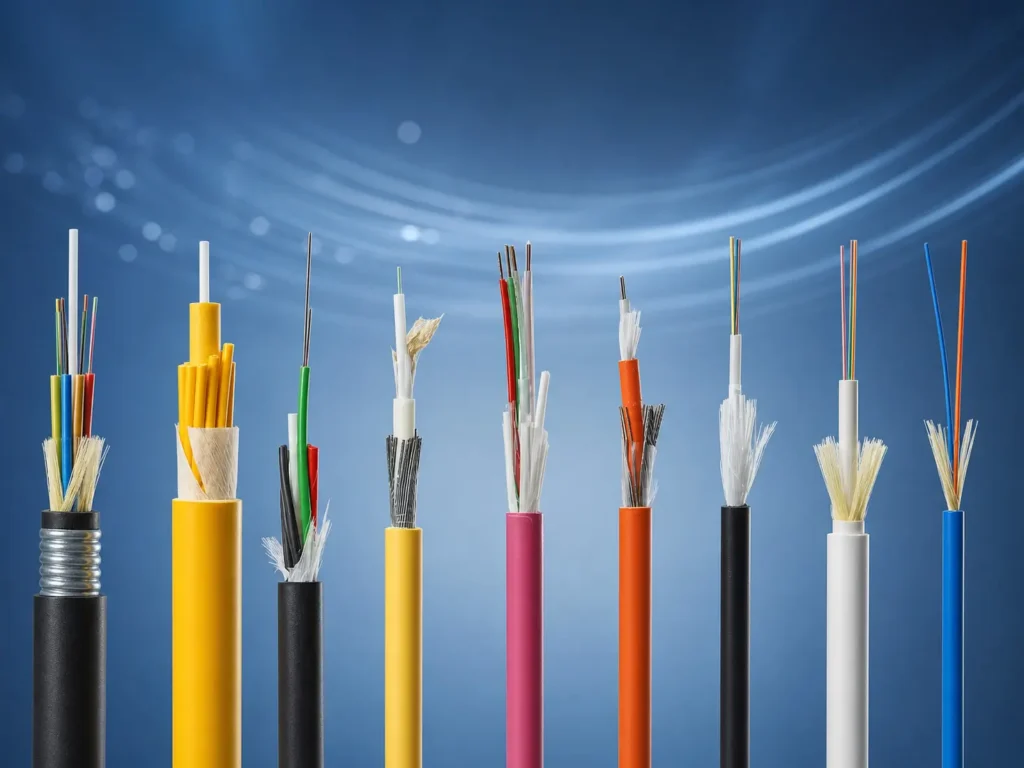
A cable may add tight-buffer layers or loose tubes, water-blocking components, reinforcement, armor, and an outer jacket. The exact stack-up depends on the route, environment, fiber count, installation method, and local safety requirements.
For example, an indoor distribution cable may prioritize flexibility, fire performance, and easy termination. An outdoor duct cable may prioritize moisture resistance, tensile performance, and weather protection. A direct-buried cable may add mechanical protection against crushing or rodent damage. No single material combination is right for every project.
Materials Inside the Optical Fiber
Silica glass core and cladding
Silica glass is the foundation of mainstream telecom optical fiber because it can transmit light over long distances with low loss when manufactured and installed correctly. The core and cladding are both glass, but their optical properties are engineered so that the core has a higher refractive index than the cladding. This difference allows the fiber to guide light by total internal reflection.
The material system is more precise than the simplified phrase “glass wire.” Fiber design can involve carefully controlled dopants and refractive-index profiles to achieve the required transmission and bending behavior. These are properties of the optical fiber design, not features created by the outer cable jacket.
Polymer coating: protecting the bare glass
Bare glass fiber is delicate. It is therefore covered with a primary coating, commonly based on UV-cured polymer systems. The coating helps protect the glass during cabling, installation, stripping, splicing, and normal handling. It also helps reduce the effect of localized pressure that can create microbending loss.
The primary coating should not be confused with a tight buffer or outer jacket. A coating is applied directly to the glass fiber. A tight buffer is an additional cable layer used in many indoor constructions, while the jacket is the outermost protective layer of the finished cable.
Single-mode, multimode, and bend-insensitive fiber
The glass fiber selected for a cable affects where that cable is normally used.
- Single-mode fiber is widely used in access, metro, long-distance, and many general telecommunications networks.
- Multimode fiber is commonly used for shorter-reach premises, enterprise, and data center links where the system is designed for it.
- Bend-insensitive single-mode fiber is designed to improve installed performance where small bend radii are expected, such as access networks, buildings, customer premises, and dense fiber-management areas; these applications are covered by ITU-T G.657.
Fiber type must be selected as part of the overall link design. A cable jacket cannot turn one fiber category into another, and a connector alone does not determine whether a link is single-mode or multimode.
Materials That Turn Optical Fiber into a Usable Cable

The protective cable structure is what allows optical fiber to survive real installation conditions. The following components are common, but not universal.
Loose tubes for outdoor protection
Many outdoor cables use loose tubes. In this construction, fibers are placed in polymer tubes with enough controlled space to help manage mechanical and temperature-related stress. Depending on the design, the tube may contain a water-blocking compound or be paired with dry water-blocking components.
Loose-tube constructions are often used for duct, aerial, and direct-buried cable designs because the cable must perform through temperature changes, pulling forces, and outdoor exposure. The tube material, fiber excess length, and water-blocking design must work together; it is not enough to specify an outer jacket alone.
Tight buffers for indoor handling and termination
Tight-buffer constructions add a polymer layer around the coated fiber. They are widely used in indoor distribution, breakout, fiber patch cord, and equipment-interconnect applications because individual fibers are easier to identify, handle, and prepare for termination.
Many indoor cables also use aramid yarn around tight-buffered fibers. This improves tensile support while preserving flexibility. The combination is particularly relevant when cable must be routed through racks, cabinets, trays, or building pathways and then terminated into connectors, adapters, panels, or enclosures.
Water-blocking materials
Water blocking is a cable-design function, not a single universal material. Manufacturers may use gel or filling compound, water-blocking tape, water-blocking yarn, or a combination of these materials. Their job is to limit the movement of water along the cable if moisture enters through damage, an end, or a weak point.
Water-blocking features are especially important for outdoor, buried, duct, and wet-route designs. For a dry indoor patch cord, the same level of water protection may not be necessary. Buyers should specify the route and environmental exposure instead of simply asking whether a cable is “waterproof.”
Strength members: steel, FRP, and aramid yarn
Strength members carry pulling loads so that the optical fibers are not asked to bear them. The material selected depends on the cable application.
- Steel can provide strong mechanical support and is used in some outdoor, armored, or self-supporting designs.
- FRP, GFRP, or other dielectric reinforcement is non-conductive and can be useful where an all-dielectric construction is preferred, such as some access, aerial, or electrically sensitive routes.
- Aramid yarn combines low weight, flexibility, and tensile reinforcement. It is commonly found in indoor cables, patch cords, tactical-style constructions, and some all-dielectric aerial designs.
The important question is not which reinforcement is universally best. It is whether the construction meets the required installation tension, electrical environment, flexibility, and long-term handling needs.
Outer Jacket Materials: PE, PVC, LSZH, and TPU
The outer jacket is the visible surface of a cable, but it should be selected for more than appearance. Jacket material influences handling, environmental resistance, and the cable’s suitability for specific installation rules.
PE and HDPE for outdoor routes
Polyethylene (PE) and high-density polyethylene (HDPE) are commonly associated with outdoor cable jackets. They are often selected for applications where weather exposure, moisture, and outdoor handling are relevant, including duct, aerial, and direct-buried designs.
The exact outdoor performance of a cable depends on the complete construction, including jacket compound, wall thickness, water-blocking design, armor where applicable, and the stated environmental rating. Therefore, an outdoor cable should be specified against the installation conditions rather than chosen simply because its jacket is black PE.
PVC for many indoor cable applications
PVC is widely used in flexible indoor cable constructions, including certain patch cords and equipment interconnects. It can be a practical choice where the applicable building code and project fire requirements permit it.
However, cable selection must follow the relevant local fire, smoke, and installation rules. A PVC jacket is not a universal answer for every indoor route, especially in buildings with specific requirements for risers, plenums, public areas, or critical infrastructure.
LSZH for applications with smoke and halogen requirements
Low-smoke zero-halogen (LSZH) compounds are commonly specified where limiting smoke and halogenated emissions is an important project requirement. They are often considered for indoor public spaces, transportation systems, data centers, and other environments governed by specific safety standards.
LSZH is a material category, not a complete fire-performance statement. Flame spread, smoke, acidity, toxicity, and installed-cable requirements should be checked against the applicable standard and project specification. Buyers should request the relevant test documentation instead of assuming that every LSZH cable performs identically.
TPU for flexible and demanding environments
Thermoplastic polyurethane (TPU) is used in cables that need high flexibility, abrasion resistance, or repeated handling. It may be relevant to industrial equipment, mobile systems, specialty indoor-outdoor assemblies, and ruggedized cable designs.
Like any jacket material, TPU should be selected according to the actual environment. Repeated flexing, abrasion, oil exposure, temperature range, and required connector protection can all affect whether it is the right choice.
Optional Protective Layers: Armor, Metal Tapes, and Specialty Materials

Armor for mechanical protection
Armored cables can add steel tape, steel wire, or another protective layer to increase resistance to crushing, impact, rodent damage, or severe installation conditions. They are commonly considered for direct-buried and high-risk outdoor routes.
Armor adds protection, but it can also add weight, diameter, stiffness, and installation complexity. It should be chosen when the route justifies it, not as a default upgrade for every outdoor cable.
Barrier layers and specialized outer protection
Some cable designs include metal-polymer laminates, glass yarn, nylon/polyamide layers, or other specialized protective elements. These may support moisture control, reinforcement, abrasion resistance, or protection against local environmental risks.
Because these details vary by cable design, use a datasheet or project specification to confirm the actual construction. A generic product name such as “outdoor fiber cable” does not reveal whether a particular cable includes armor, water blocking, dielectric reinforcement, or a specialty jacket.
How to Choose Cable Materials by Installation Environment
The quickest way to select a cable is to start with the installation environment and then work inward toward fiber type, construction, and termination requirements.
| Installation environment | Material priorities | Common construction direction | Questions to confirm |
|---|---|---|---|
|
Data center |
density, bend management, indoor safety requirements |
tight-buffer fiber, aramid reinforcement, PVC or LSZH jacket as specified |
fiber type, polarity, connector format, fire requirement |
|
Office or building |
flexibility, indoor routing, easy termination |
tight-buffer distribution or breakout cable |
local cable rating, bend radius, transition to outlets or panels |
|
FTTH drop |
compact size, bend performance, tensile support |
bend-insensitive fiber with dielectric or metallic reinforcement as required |
self-supporting need, indoor/outdoor transition, termination method |
|
Duct or aerial route |
moisture protection, tensile load, weather exposure |
loose tube, water blocking, outdoor PE-type jacket |
route length, pulling load, UV exposure, electrical environment |
|
Direct burial |
moisture, crush, rodent, and installation protection |
water blocking plus armor or reinforced structure where required |
soil conditions, burial method, mechanical risk, repair access |
|
Industrial or mobile use |
flexibility, abrasion, repeated handling |
aramid reinforcement and a specialty jacket such as TPU where appropriate |
flex cycles, abrasion, oil exposure, connector protection |
This table is a starting point, not a substitute for a project specification. In particular, fire ratings, mechanical ratings, and environmental limits need to be matched to the required standard and actual installation route.
Why Cable Materials Matter for Termination and Connectivity
Cable material selection and connectivity planning should be considered together. A reliable network depends not only on the attenuation of the fiber, but also on how the cable will be broken out, protected, terminated, tested, and maintained.
Fiber type and cable construction affect the connection plan
Single-mode and multimode systems require compatible components and test methods. Fiber count determines how many terminations, splice trays, adapters, or high-density interfaces may be needed. A loose-tube outdoor cable may need to be transitioned through a closure or breakout arrangement before entering a building, while a tight-buffer indoor cable may be prepared for direct termination more easily.
High-fiber-count MPO trunks introduce additional planning questions, such as connector format, polarity, cassette layout, and future expansion. These decisions should be made before installation rather than after cable has been routed into a crowded cabinet or pathway.
Installation conditions influence component selection
Jacket material, cable diameter, bend-radius requirements, water exposure, armor, and route type all influence the supporting hardware. A cable installed in a data center has different requirements from an aerial cable, an FTTH drop, or a direct-buried route.
For example, a harsh outdoor route may require protected splice management and an enclosure designed for the cable’s entry and sealing method. An indoor high-density route may prioritize patch-cord bend management, adapter layout, compatible fiber optic connectors. The cable and connection system should be specified as one deployment plan.
Plan the cable and connection system together
Before placing an order, confirm the following together:
1. Fiber type and fiber count.
2. Installation route and environment.
3. Required jacket and fire-performance specification.
4. Water-blocking, dielectric, armor, or reinforcement needs.
5. Minimum bend radius and pulling constraints.
6. Termination method: splice, field connector, pre-terminated assembly, or high-density trunk.
7. Required connector interface, polarity, adapter, enclosure, and testing plan.
This approach avoids a common procurement problem: choosing cable only by fiber count and price, then discovering later that the intended termination or installation method is not compatible with the selected construction.
A Practical RFQ Checklist for Fiber Cable Projects
When requesting a quotation or comparing options, provide as much of the following information as possible:
- Required fiber type: single-mode, multimode, or bend-insensitive fiber.
- Required fiber count.
- Installation environment: indoor, outdoor, aerial, duct, direct-buried, industrial, or mixed route.
- Expected temperature, moisture, UV, abrasion, or mechanical exposure.
- Need for water blocking, dielectric construction, armor, or rodent protection.
- Fire, smoke, or halogen requirement for the installation location.
- Cable length, reel length, and pulling method.
- Minimum bend-radius requirement.
- Termination approach and required connector interface.
- Need for compatible patch cords, adapters, enclosures, splice closures, or MPO/MTP assemblies.
Clear RFQ information leads to a more accurate recommendation and helps prevent compatibility issues between cable, connectivity products, and installation hardware.
Frequently Asked Questions
What material is optical fiber made of?
Most telecommunications optical fiber is made from highly purified silica glass. The light travels in a glass core surrounded by glass cladding with a different refractive index, while polymer coatings protect the glass from handling and environmental stress.
Are fiber optic cables made of glass or plastic?
Both materials can be present. The light-carrying fiber in mainstream telecom cable is normally glass, while the protective coating, buffer, loose tube, strength members, and jacket are commonly polymer-based materials. Some short-reach specialty optical fibers are polymer optical fibers, but they are not the standard choice for most telecom networks.
What is the difference between fiber coating and cable jacket?
The coating is a thin polymer layer applied directly over the glass fiber. The jacket is the outer protective layer of the finished cable. Between them, a cable may also include a tight buffer or loose tube, reinforcement, water blocking, and armor.
What is the difference between PVC, LSZH, PE, and TPU cable jackets?
PVC is common in many flexible indoor constructions. LSZH is used where the project requires low-smoke, halogen-free materials. PE or HDPE is common in outdoor constructions, while TPU is often chosen where flexibility and abrasion resistance are important. The correct material depends on the route and applicable specification.
Why do some fiber optic cables use aramid yarn?
Aramid yarn adds tensile support without adding much weight and can preserve flexibility. It is often used in indoor, patch-cord, breakout, and some specialty cable constructions.
When is armored fiber cable necessary?
Armor may be appropriate where crushing, rodent damage, impact, or direct-burial conditions create a material risk. It is not automatically required for every outdoor cable because armor also increases diameter, weight, and stiffness.
Does cable material affect the connectors and patch cords I need?
Yes. Fiber type, fiber count, cable construction, breakout method, bend requirements, installation environment, and termination method all influence the compatible connection plan. Confirm these factors before selecting connectors, patch cords, adapters, enclosures, or high-density assemblies.
Conclusion
The right fiber optic material is not simply the strongest or most expensive option. It is the combination of optical fiber design, protective cable structure, reinforcement, and jacket material that matches the installation environment and the connection plan.
Start with the route: where the cable will be installed, what it must withstand, how it will be terminated, and how the network will be maintained. From there, select the fiber type and material stack-up that meet the actual requirements. This makes it easier to build a cable and connectivity solution that is practical to install, reliable in service, and ready for future expansion.
For help comparing fiber cable and connectivity options, share the installation environment, fiber type, fiber count, and termination requirements with our team.