
TABLE OF CONTENTS
An optical distribution frame (ODF) is the central point where fiber cables are terminated, spliced, protected, labeled, and patched to the next part of a network. In simple terms, it turns a bundle of incoming fibers into organized, serviceable circuits. Technicians can identify each route, test it, move it, and restore it without disturbing the rest of the installation.
An ODF is used wherever a fiber network needs more than a few simple connections: telecom central offices, ISP points of presence, data centers, enterprise equipment rooms, campus backbones, and some FTTH or FTTB distribution points. Its value is not the metal enclosure alone. A well-planned ODF protects fragile fiber, controls bend radius, stores slack, supports accurate labeling, and keeps future changes manageable.
If you are selecting an ODF, start with the work it must support rather than with the number of ports on the front panel. The right choice depends on cable entry, splicing method, connector format, access requirements, density, protection, and planned growth.
ODF vs. Fiber Patch Panel vs. Fiber Enclosure

These terms are often used interchangeably, but they describe different levels of fiber-management capability. A patch panel primarily provides connector termination and cross-connect access. A fiber enclosure is generally a compact protective housing. An ODF is the more complete management system for termination, splicing, routing, protection, and larger-scale distribution.
| Feature | Optical Distribution Frame (ODF) | Fiber Patch Panel | Fiber Enclosure |
| Primary role | Centralize fiber termination, splicing, patching, routing, protection, and records. | Provide accessible connector termination and patching. | Protect and organize a smaller fiber termination or splice point. |
| Splicing support | Common; often uses dedicated splice trays and cable-entry management. | Limited or product-specific. | Common on a smaller scale. |
| Typical capacity | Medium to very high, from rack-level systems to large central-office frames. | Low to medium, depending on rack units and adapter plates. | Low to medium. |
| Best fit | Telecom rooms, central offices, data centers, campus backbones, and scalable distribution. | Equipment racks and straightforward cross-connects. | Small buildings, access points, local termination, or compact distribution. |
The boundary is practical, not merely a naming convention. If your team needs to bring in outside-plant cable, splice pigtails, store service loops, patch circuits, keep records, and scale beyond a small rack, an ODF-style solution is usually the better starting point.
What Is Inside an Optical Distribution Frame?

The exact layout varies by product, but a useful ODF normally combines several functional zones. Keeping those zones separate is what makes the system safe and maintainable.
- Cable entry and strength-member fixation: secure incoming cable before fibers are routed into the frame.
- Splice trays and protection holders: organize fusion splices or other approved splice methods and protect the completed work.
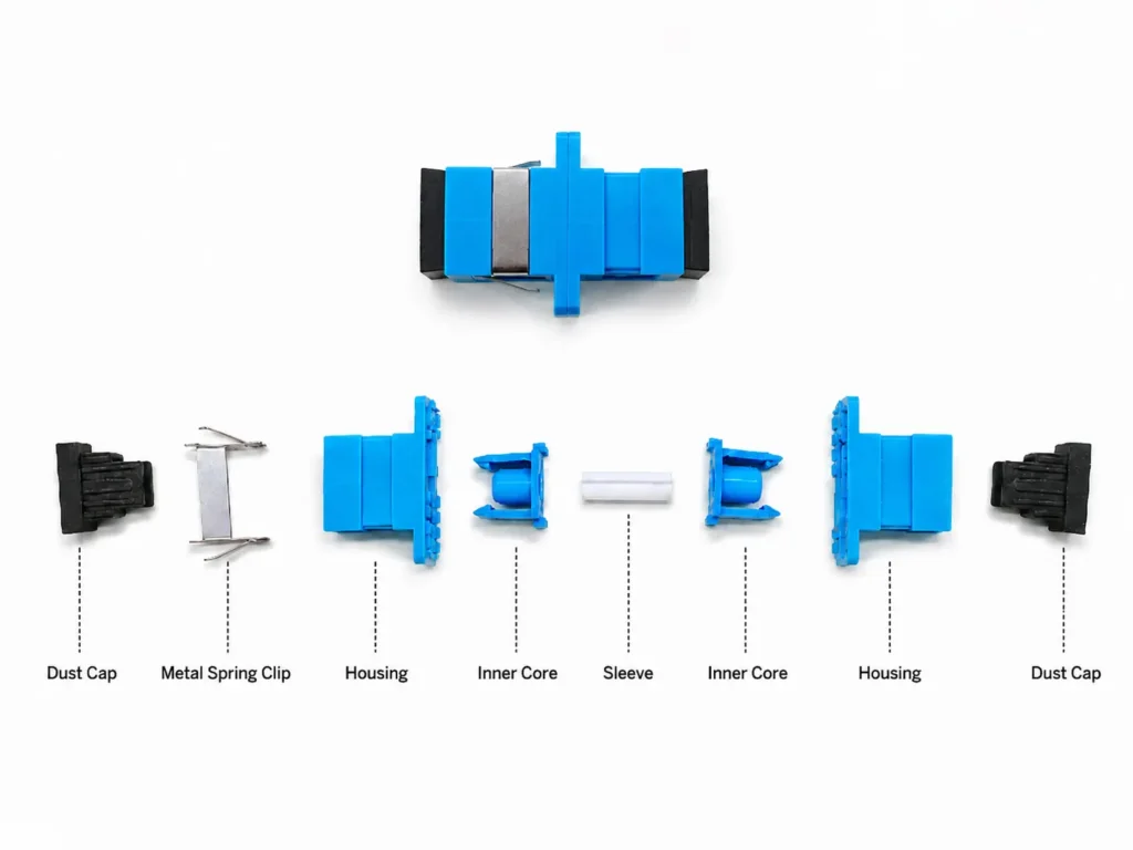
- Pigtails and adapter plates: provide the transition from spliced fiber to a connectorized, serviceable interface.
- Routing guides and slack storage: keep fibers on controlled paths and prevent tight bends, pinches, and uncontrolled loops.
- Labeling areas and port records: make it possible to identify a circuit without tracing every fiber by hand.
- Doors, covers, and access zones: protect fiber from dust and accidental contact while allowing technicians to work efficiently.
When comparing products, inspect the internal routing path as closely as the front-panel port count. A frame that looks dense on paper but provides poor front/rear access, inadequate slack storage, or no clear route separation can become expensive to operate.
ODF Types and Where They Fit
Wall-Mount ODF

Rack-mount ODFs are designed for standard equipment racks and are common in enterprise networks and data centers. They may be supplied in 1U, 2U, 4U, or larger modular formats. A rack-mount design is often the practical choice when active equipment, patch cords, and fiber management need to remain in one controlled rack environment. Confirm the rack standard, depth, drawer travel, front/rear access, and cable exit direction.
Rack-Mount ODF

Wall-mount ODFs are compact units used in low- to medium-fiber-count locations such as small telecom rooms, campus buildings, FTTH/FTTB distribution points, and local equipment areas. They are appropriate when floor space is limited and the network needs basic splicing, termination, and patching in one protected location. Check wall clearance, cable-entry direction, door swing, and service access before choosing this format.
Floor-Mount or Main Distribution Frame
Floor-mount systems are intended for high fiber counts, large trunk cables, and carrier or central-office environments. They provide more space for cable entry, vertical routing, splice management, and future modules. This format is appropriate when the facility must accommodate hundreds or thousands of fibers and changes must be made without creating congestion.
High-Density and Pre-Terminated ODF Systems
High-density ODFs are designed for fiber-rich data-center and transport environments. They often use modular cassettes, LC adapter plates, or MPO/MTP connectivity to increase density while retaining access. Pre-terminated systems can reduce on-site termination work and deployment time, but they require accurate planning for trunk length, polarity, connector format, and routing before purchase.
How to Choose an ODF: 7 Procurement Questions
1. How many fibers are active now, and what growth is realistic?
Start with the current fiber count, then add capacity for approved expansion, spare routes, and future equipment changes. Do not rely on a universal growth percentage; project standards, building plans, and network architecture should define the reserve. Also check whether the stated capacity includes splicing, adapter plates, and cable-entry hardware, not just an empty front-panel count.
2. Will the ODF support splicing, patching, or both?
A patch-only workflow has different requirements from a splice-and-patch workflow. If incoming cable must be spliced to pigtails, verify tray capacity, splice-protection holders, cable clamp hardware, and the route from tray to adapter plate. If the ODF is a cross-connect point, prioritize access, labeling, patch-cord routing, and clean separation between working and spare circuits.
3. Which connector and fiber ecosystem must it support?
A patch-only workflow has different requirements from a splice-and-patch workflow. If incoming cable must be spliced to pigtails, verify tray capacity, splice-protection holders, cable clamp hardware, and the route from tray to adapter plate. If the ODF is a cross-connect point, prioritize access, labeling, patch-cord routing, and clean separation between working and spare circuits.
4. Does the form factor fit the room and rack?
For rack systems, verify 19-inch or other rack standards, available rack units, depth, cable entry, bend-radius space, and clearance for drawer or door operation. For wall-mount systems, verify installation height, wall capacity, cable approach, and technician working space. For floor-mount systems, confirm row layout, overhead or underfloor routing, and service aisles.
5. Can technicians work without disturbing live circuits?
Good manageability reduces mean time to repair. Look for clear routing channels, enough slack storage, separated splice and patch areas, readable labels, and access that does not require moving unrelated patch cords. In high-density systems, front access and modular replacement can be as important as the raw port count.
6. How will the ODF protect fiber over time?
Fiber must be protected from excessive bending, pull force, dust, and accidental contact. Review the manufacturer’s routing guidance, cable clamp design, radius-control features, cover design, and environmental suitability. If the site is exposed to vibration, dust, or severe temperature conditions, include those requirements in the specification rather than treating them as optional extras.
7. What documents should be requested before approval?
Request dimensional drawings, port/adapter layout, cable-entry details, compatible accessories, fiber-routing guidance, bill of materials, and relevant test or inspection records. For OEM projects, also confirm labeling, packaging, color, logo, and documentation requirements before production.
Application Examples
Telecom Central Office or ISP Point of Presence

A carrier or ISP environment often requires high-count fiber management, robust cable entry, clear cross-connect capacity, and disciplined labeling. Floor-mount or larger frame systems are common where many feeder, distribution, or transport circuits meet. The specification should focus on capacity, cable routing, access safety, growth modules, and documentation.
Enterprise Data Center

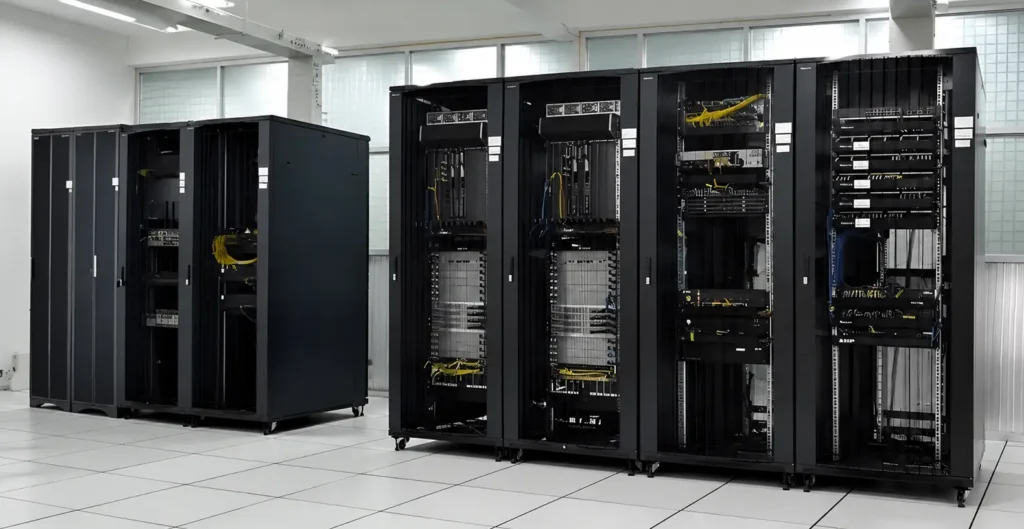
Image Source: Chinedu Godfirst Ezenwangwa
In a data center, the ODF may serve as a structured cross-connect between backbone trunks, cassettes, patch cords, and active equipment. High-density LC or MPO/MTP designs can support migration paths, but density should never compromise access or polarity control. Plan the path from MPO trunk to LC breakout, the direction of patch-cord exits, and the separation of redundant A/B routes.
Campus or Multi-Building Network
Campus deployments typically need reliable backbone termination between buildings and telecom rooms. Rack-mount or wall-mount ODFs may be appropriate depending on fiber count and room constraints. The key is a consistent labeling system, enough spare capacity, controlled slack storage, and a clear record of every building-to-building route.
Installation and Operations Checklist
Use the following checklist as a project-control aid. It does not replace the installation instructions for the selected ODF or the site’s safety and acceptance standards.
| Before installation | During commissioning | For ongoing operations |
| Confirm location, rack/wall compatibility, cable entry, component list, and required tools. | Record cable IDs, tray positions, adapter ports, splice results, and test records. | Keep port records current whenever a patch is moved, added, or removed. |
| Verify routing space and the required minimum bend radius for the cable and product system. | Check that fiber routes are protected, covers are fitted, and live circuits remain undisturbed. | Inspect for congestion, dust, damaged patch cords, unlabeled ports, and uncontrolled slack. |
| Prepare a labeling plan before fibers enter the frame. | Validate connector type, polarity where relevant, and the agreed acceptance test method. | Use controlled change procedures so the physical ODF and the network record stay aligned. |
Frequently Asked Questions
What is the difference between an ODF and a fiber patch panel?
A patch panel mainly provides connector termination and patching. An ODF is designed to manage a broader workflow that can include incoming cable, splicing, protection, slack storage, routing, labeling, and higher-capacity distribution.
How do I choose ODF capacity?
Count active fibers, approved growth, spare routes, splice requirements, adapter positions, and cable-entry needs. Check how the supplier defines capacity, because a front-panel port count alone may not reflect the complete usable configuration.
Should I use LC or MPO/MTP in an ODF?
LC is common for equipment-side distribution and duplex links. MPO/MTP is often used for high-density trunks and parallel-optics architectures. Many systems use MPO/MTP trunks with LC breakout cassettes; the right choice depends on the full cabling design.
Why are bend radius and labeling so important?
Excessive bending can increase optical loss or damage the fiber. Clear labels reduce troubleshooting time and lower the risk of changing the wrong circuit. Both practices protect service continuity.
Can an ODF be customized for an OEM project?
Many ODF configurations can be customized by capacity, adapter plate, cable-entry arrangement, color, labeling, packaging, and branding. Confirm the technical drawing and bill of materials before production.
Plan an ODF That Stays Serviceable
The best ODF is not simply the one with the highest port count. It is the one that fits the network’s current circuits, protects fiber correctly, gives technicians clear access, and leaves room for controlled growth. A short planning review before procurement can prevent years of avoidable congestion and troubleshooting.
If you are defining an ODF for a telecom, campus, FTTH, or data-center project, review the required configuration with the product drawing, cable plan, connector format, and installation workflow together. For product options and a configuration discussion, visit YingFeng’s Optical Distribution Frame page.