
TABLE OF CONTENTS
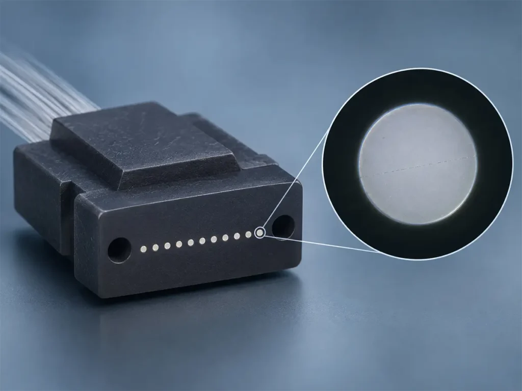
Anyone who has run MT-FA in volume knows the moment. The end face on the inspection screen is polished bright and flat, and a thin dark line runs across one of the fibers. It looks like dust. You clean it and look again, and it’s still there.
That’s a cracked fiber. We recently worked through a batch of them and traced two causes for certain: the tail adhesive pre-cure was running too hot, and the laser stripper’s power was set too high. Fixing those two took care of part of the problem, not all of it. Below are the crack patterns we keep seeing, what we changed, the suspects we haven’t cleared yet, and how we use the shape of a crack to decide where to look first. It’s the first entry in our MT-FA production notes.
What a Cracked Fiber Looks Like on an MT-FA End Face
First, the part itself. An MT-FA joins an MT ferrule, molded from glass-filled PPS, to a fiber array, and we build it with both single-mode and multimode fiber. The cracks we’re talking about sit in the glass fibers exposed on the polished MT face, not in the ferrule body.
Don’t confuse it with a scratch. A scratch is surface damage; a crack is structural: a real fracture through part or all of the fiber end, with a clean, sharp-edged break that shows on the scope as a dark line or a dark patch. Silica glass is brittle, so once a fiber cracks there is nothing to rework. The part is scrap.
Cracks don’t all look alike. These are the three patterns we catch most often, worth saving if you inspect MT-FA end faces yourself.
Pattern 1: A Straight Crack Through the Middle

The crack runs straight across the core area. When we see this one, the fiber has usually broken right through inside, and the stress almost always came from a step before polishing. Curing stress and heat damage from stripping are the two we check first.
Pattern 2: An Arc of Linked Cracks From the Edge

This one starts at the edge of the end face and works inward as a broken, curved line. The shape points fairly clearly at force on the edge: stress piling up there during polishing, or the protective layer on the end face starting to lift.
Pattern 3: A Sideways Crack Near the Edge

Still on the edge side, but by now it’s one continuous line. We think of it as pattern 2 further along, with the small edge cracks grown and joined up. We haven’t caught one changing from one shape into the other, so take that as our reading rather than something we’ve proven.
Why sort by shape at all? Because where a crack sits and which way it runs are clues. A center crack and an edge crack send you down different paths, and we come back to that further down.
Confirmed Cause 1: Tail Adhesive Pre-Cure Running Too Hot
The tail adhesive sits where the fibers leave the V-grooves of the fiber array. It stays in the product for good, holding the fibers in place and taking bending and pulling loads before they reach the glass. We pre-cure it with heat in three stages.
That pre-cure was set to 110°C. We brought it down to 95–100°C and held the pre-cure time to about 13 seconds. That one change cleared up part of the cracking.
Why would cure temperature crack a fiber? Thermal expansion. The materials around the fiber react to temperature very differently. Fused silica expands only about 0.5 ppm per °C,[1] while the epoxies one fiber optic supplier lists for terminations run from roughly 30 to almost 90 ppm per °C.[2] The glass-filled PPS ferrule falls somewhere in between.
As the part cools after curing, the adhesive wants to shrink a lot, the silica hardly shrinks at all, and the ferrule sits in the middle. They pull against each other, and the stress ends up locked onto the fiber surface. The hotter the cure and the earlier the adhesive sets hard, the bigger that cooling mismatch, and the less chance it has to relax. Sooner or later it shows up as microcracks in the glass. Most of the stress built into a cured adhesive comes from shrinkage after the gel point, and a higher cure temperature means more thermal stress. Adhesive suppliers to the fiber optic industry see the same pattern. They recommend the lower of the allowed cure temperatures, and some assembly houses get good results from a ramped oven instead of putting parts straight into a hot one.[2]
One thing we’d pass on: the pre-cure isn’t there to cure the adhesive. Its job is to hold the shape. Use enough heat to do that, keep the time short, and leave the real crosslinking to the post-cure.
Confirmed Cause 2: Laser Stripper Power Set Too High
The second cause was the laser stripper. Its power was too high, and it was burning the fiber during stripping.
A laser stripper vaporizes the coating. Done right, the coating absorbs the heat and carries it off, and the silica underneath is left alone. Push the power too far and energy gets through the coating to the cladding surface. That sudden heat shock can leave microcracks and stressed zones in the glass that nobody can see. Laser makers flag the same risk: the CO2 and UV lasers most strippers use are absorbed by glass as well as by polymer, so they can affect the glass under the coating and lower the fiber’s mechanical strength.[3]
What makes this cause hard to catch is that nothing looks wrong when stripping is done. The fiber moves on down the line. Later, polishing pressure, cooling after cure, or even handling makes those microcracks grow and join, and only then does the crack appear. So the crack shows up at polishing, but the damage was done at stripping.
The controls engineers usually point to come down to three things:
- Match the laser settings (power, pulse width, scan frequency) to the coating material and thickness.
- Keep the focus inside the coating layer. Don’t let it sink toward the cladding.
- Get scan speed and air cooling working together so leftover heat is carried away.
We checked ours, turned the power down, and the burn-type cracks dropped noticeably.

Still Open: Our Suspect List
With both causes fixed, some cracked fibers still had no explanation. So we gathered every cause we could find and sorted them by how likely they look to us. This is our working list for the next round:
- Wrong amount of protective adhesive on the end face. Before polishing, a peelable protective layer goes over the fibers on the MT face and comes off afterwards. Too big, too thick or too thin, and it can come away in one piece during polishing. The fibers lose support in that spot, stress piles up, and the glass breaks. This came up more than anything else in what we read.
- Uneven polishing pressure or vibration. Unstable speed, a machine that doesn’t run smoothly, or loose clamping in the fixture all put more, and less even, stress on the fibers. Fiber ends left standing proud are a particular risk: under polishing pressure they can snap and break below the ferrule surface.[4]
- Abrasive shedding from the polishing film. Loose grains get rolled across the end face. Besides scratches, they deliver small impact loads.
- Hidden damage from coarse grits. What a coarse film leaves behind has to be fully removed by the finer steps after it, and a skipped grade or a short fine step may not get there.[4] Our worry is that this damage then waits for a later step to grow, which would explain an end face that passes inspection and cracks afterwards. Keep the grits stepping down, and don’t make the jumps too big.
- Stress from the main adhesive cure. The main cure brings its own chemical shrinkage. A thick adhesive layer carries more stress in its center than at its edge, so the cure profile should ramp up and down in stages.
- Dirt and debris. A particle on the end face during polishing or mating becomes a point load and can press a microcrack straight into the glass.
- Knocks to bare fiber. Between stripping and going into the ferrule, the bare fiber is exposed. Any bump in that window can leave a starting point for a crack.
We haven’t checked items 1 to 3 properly yet. Those are the next cases to close. We’re writing the list down partly as a record and partly so that anyone chasing the same problem has somewhere to start.
Let the Crack Tell You Where to Look
Back to the point from the start: the shape of a crack can steer you toward the step behind it. This is how we use it.
| What you see | What it suggests | Check first |
|---|---|---|
| Crack in the middle, running straight | Stress on the fiber as a whole, from the way it is held | Cure temperature, adhesive amount, adhesive cure stress |
| Crack at the edge, curved or a broken chain | Force concentrated at the edge | Protective layer condition, how even the polishing pressure is, fixture clamping |
| No crack at inspection, crack appears later | A hidden crack that was already there | Stripping burns (check the stripped bare fiber with side lighting), grit steps in polishing |
It isn’t a rule. It’s the order we work in, and it has saved us time.
Two Habits That Helped
Track where the cracks sit. For every cracked fiber, note the position: center, edge, which quadrant. Keep it up for two weeks. The main cause tends to show itself.
Inspect in both bright field and dark field. Very fine cracks are close to invisible in bright field. Dark field or backlighting brings them out. Fiber optic suppliers make the same point about cracks below the surface: without backlighting they can look like a faint dark curve that an operator writes off as a lighting effect.[2] We suspect this is how a lot of lines miss cracked fibers.
What We Took Away
After this round, the main lesson is that a cracked fiber isn’t one cause. It’s a kind of symptom. The same end-face pattern can come from the cure profile, the laser settings, the polishing pressure or the way the protective adhesive went on.
So don’t expect one fix to clear everything, and don’t expect anyone to hand you a universal parameter. Sort the crack patterns, start counting, and let the data show the way. That approach works for any volume production problem, not just this one.
For the polishing side in more detail, see our article on the MT ferrule polishing process, and for where polishing fits in the whole build, the MPO patch cord manufacturing process.
MPO/MTP Patch Cords With Test Records
MPO/MTP Patch Cords: 8-, 12-, 16- and 24-fiber assemblies, with measured IL/RL data and end-face inspection records for each cord View MPO/MTP patch cords
If end-face quality matters on your project, we can supply measured insertion loss and return loss data and end-face inspection records for each of our MPO/MTP patch cords, and samples are available on request. Tell us your fiber count and acceptance criteria and we’ll come back with options.
Frequently Asked Questions
Can a cracked fiber be fixed by re-polishing?
No. The fracture runs into the glass, not just across the surface, so a little more polishing won’t take it out. Silica is brittle, and once it cracks the part is scrap. That’s why it pays to find the cause instead of just sorting out the rejects.
How can I tell a crack from a scratch or dirt?
Clean the end face and inspect again first; dirt usually moves or disappears. A scratch is a surface mark, often following the polishing direction. A crack is a sharp, clean break that stays put after cleaning. If you’re still not sure, switch to dark-field or backlit inspection, where cracks are much easier to see.
Why do cracks show up at polishing if the cause came earlier?
An earlier step can leave microcracks that look like nothing at the time. Laser burns during stripping and stress locked in during curing are two examples. Polishing pressure, cooling or handling then makes them grow until they’re visible.
Will lowering the pre-cure temperature stop fiber cracks?
External references
- Corning: HPFS 7979, 7980, 8655 Fused Silica (product brochure)
- Fiber Optic Center: Does Epoxy Cause Core Cracking? Tips to Identify and Prevent This Phenomenon (technical article)
- Femtum: Selective Laser Processing Part 1: Optical Fiber Laser Stripping (technical article)
- SENKO Advanced Components: Polishing Best Practices (application note, 2023)