
TABLE OF CONTENTS
An MPO cable can fit the intended port and still be wrong for the link. The fiber count may not match the transceiver, the polarity may not provide the required transmit-to-receive path, or both ends may use the wrong pin configuration. These errors often remain hidden until installation, when correcting them becomes slower and more expensive.
In our specification reviews for custom cable projects, the recurring problem is rarely a complete lack of product information. It is usually that important details are spread across equipment documents, cabling drawings, bills of materials, and purchasing notes without being reconciled into one cable specification.
That is why an MPO/MTP patch cord should not be ordered from a short description such as “12-fiber multimode cable.” A usable specification must describe the complete connection: equipment interfaces, cable architecture, fiber mapping, connector configuration, optical performance, installation environment, and testing requirements.
The following process turns those decisions into a procurement-ready specification for data centers, telecom rooms, enterprise backbones, and other high-density fiber networks.
MPO vs. MTP—and Patch Cord vs. Trunk or Breakout Cable
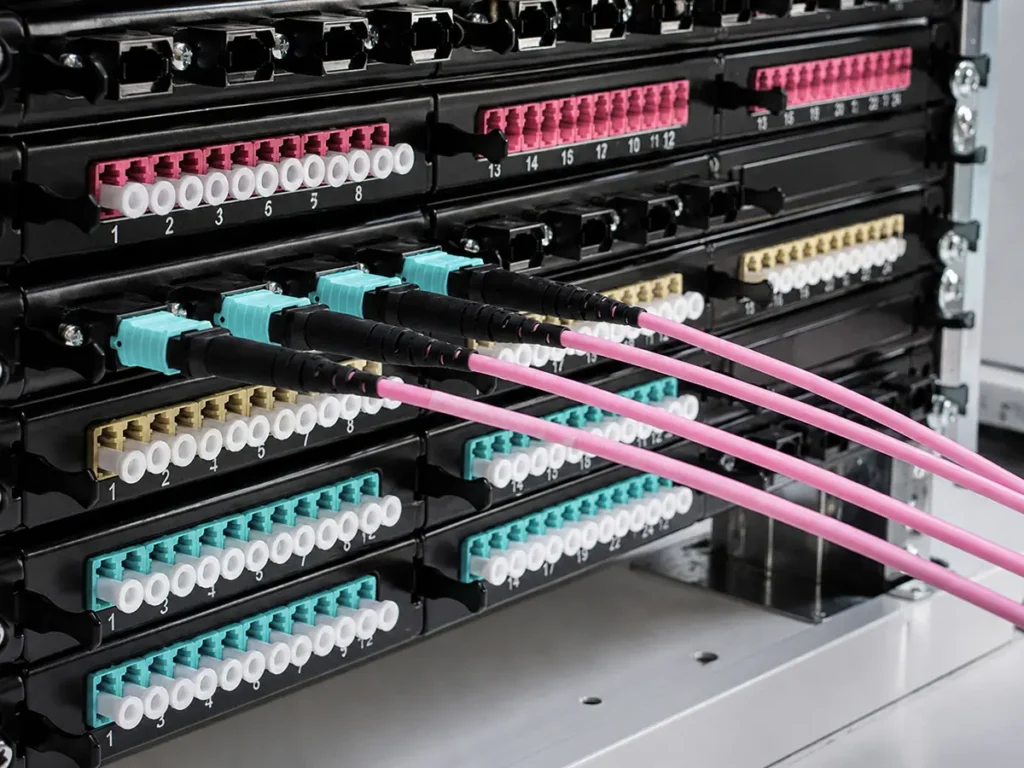
MPO stands for “multi-fiber push on.” Instead of terminating a single fiber, an MPO connector aligns an array of fibers in one compact interface. The IEC 61754-7 family defines interface dimensions for the MPO connector family, while TIA-604-5, also known as FOCIS 5, is commonly referenced in the United States.
MTP® is not a separate generic connector category. It is US Conec’s branded, high-performance MPO connector. An MTP connector is therefore an MPO connector, but a generic MPO connector should not automatically be described as MTP. US Conec provides a useful explanation of the MPO and MTP relationship. Procurement documents should state whether genuine MTP® components, MTP-compatible assemblies, or standards-compliant generic MPO components are required.
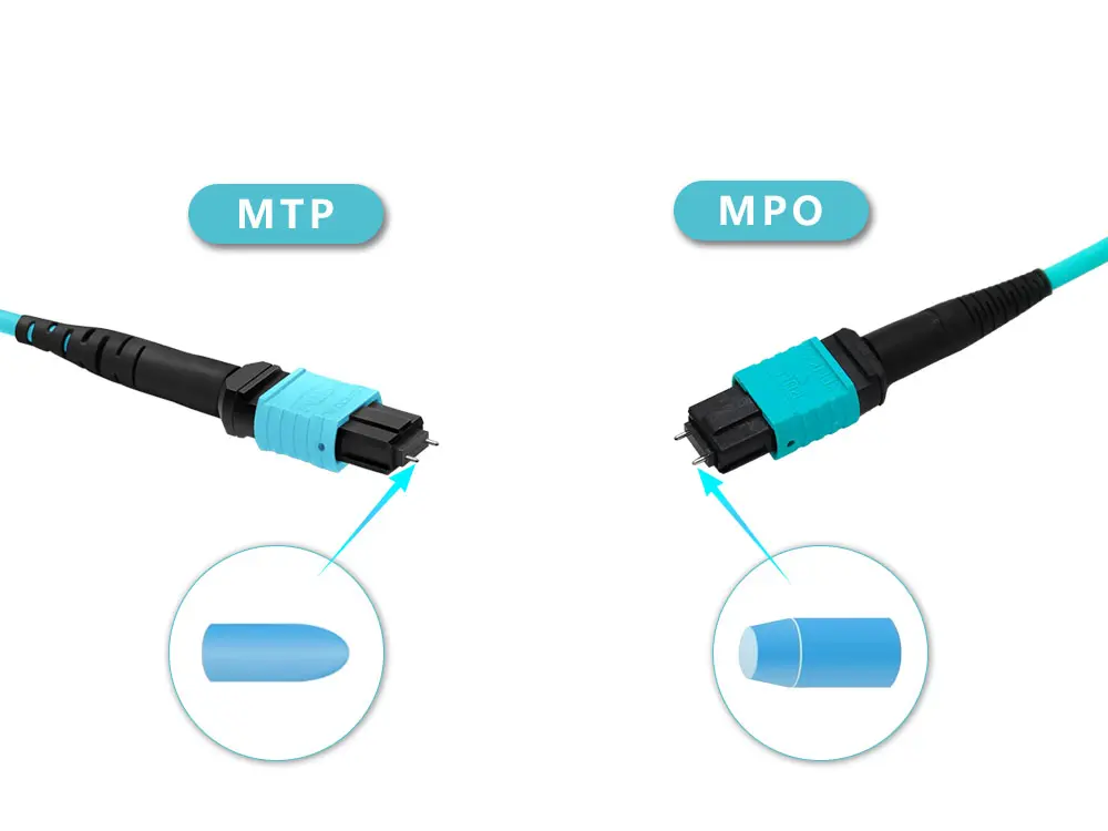
Cable terminology also varies. “MPO patch cord” and “MPO patch cable” are frequently used for the same assembly, but trunk and breakout describe different functions:
- An MPO-to-MPO trunk cable carries multiple fibers between panels, cassettes, or network zones.
- An MPO-to-LC or MPO-to-SC breakout cable, also called a harness or fanout, separates the multifiber interface into duplex or simplex equipment connections.
- A conversion assembly maps one MPO format to another, such as a higher-fiber-count connector breaking out to several lower-fiber-count MPO connectors.
These multifiber assemblies complement conventional fiber optic patch cords used for LC, SC, FC, ST, and other single-fiber or duplex connections. Choosing the correct assembly starts with the link—not with the cable catalog.
Step 1: Define the Link and Equipment Interfaces
Draw the connection from one active device to the other before selecting the assembly. Identify every transceiver, adapter, cassette, patch panel, and intermediate connection in the channel. For each endpoint, record the connector format, required fiber count, pin condition, key orientation, and end-face requirement.
This prevents a common specification mistake: selecting a cable based only on the network speed. Two links operating at the same nominal speed may use different optical interfaces, lane counts, or breakout designs. The transceiver specification and approved cabling architecture—not a simplified speed-to-cable chart—should determine the fiber mapping.
The link drawing should also show whether the new cable is being used for direct equipment connection, permanent backbone cabling, cross-connect deployment, or migration from an existing LC-based system. These applications may require very different MPO assemblies even when the fiber type is identical. For a broader view of how patch cords, trunks, panels, and distribution hardware work together, review our data center fiber optic solutions.
Step 2: Choose the Cable Architecture and Fiber Count

Once the interfaces are known, select the assembly that connects them without unnecessary transitions.
An MPO-to-MPO trunk is normally appropriate when high-density panels or cassettes terminate both ends of a backbone. An MPO-to-LC breakout is useful when a parallel or aggregated MPO link must connect to individual LC ports. Conversion cables can support migration projects, but their fiber mapping must be documented carefully so that technicians understand how each lane is routed.
Fiber count is part of this architecture decision. Common configurations include 8, 12, and 24 fibers, while higher-count trunks may combine multiple rows or subunits. More fibers do not automatically make a cable more suitable. The correct count is the one that matches the optical interface, channel design, and future migration plan without leaving critical lanes incorrectly mapped.
Before releasing the bill of materials, confirm the fiber count, cable architecture, polarity, length, and test requirements. For a breakout assembly, document both the trunk-side connector and every branch. “MPO-12 to LC” is incomplete; the request should identify the number of LC connectors, simplex or duplex arrangement, branch length, labeling sequence, and lane mapping.
Step 3: Match the Fiber Type and End Face
Fiber type must match the optical system. OS2 single-mode fiber and OM3 or OM4 multimode fiber are not interchangeable, and their supported reach depends on the transceiver, wavelength, link loss, and network standard. Confirm these conditions with the equipment documentation rather than choosing fiber from jacket color alone.
The connector end face must also match the system interface. Single-mode MPO applications often use an angled physical-contact design, while multimode systems commonly use a non-angled physical-contact interface. However, the purchasing specification should state the required end face explicitly instead of relying on a general convention.
Do not mix incompatible end-face types within a mated connection. A mismatch can prevent correct physical contact and may introduce unacceptable loss or reflection. If a cable has different connector families at each end—for example, MPO/APC to LC/UPC—list the end-face requirement separately for Connector A and Connector B.
Step 4: Verify Polarity, Key Orientation, and Pin Configuration
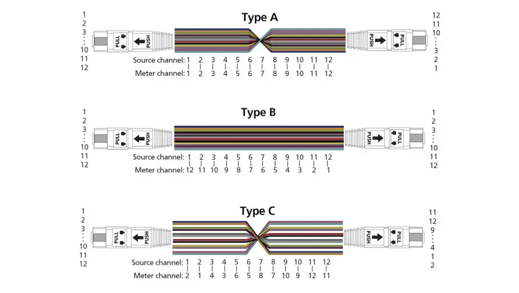
Polarity describes how transmit fibers reach the correct receive fibers across the complete channel. It cannot be confirmed by looking at only one cable segment.
At the cable level, three mapping patterns are commonly discussed:
- Type A provides a straight-through position mapping.
- Type B reverses the fiber array from one end to the other.
- Type C flips adjacent fiber pairs.
These labels describe cable mapping, but they do not by themselves guarantee a working end-to-end link. Cassettes, adapters, patch cords, and transceiver interfaces all affect the final polarity. The selected method should be checked against the complete channel design and the applicable cabling documentation, such as ANSI/TIA-568.3-E.
Key orientation and pin configuration are separate decisions. A pinned connector—often called male—contains alignment pins. An unpinned connector—often called female—contains the corresponding guide holes. A valid mated pair normally needs one pinned and one unpinned interface. The adapter aligns the connector housings; it does not remove the need to specify the correct pin arrangement.
For clarity, add a simple fiber map to the purchase drawing. Show connector keys, pin condition, fiber positions, and the mapping from Connector A to Connector B. For breakout cables, show the relationship between each MPO lane and each LC or SC branch label. This small drawing prevents more ambiguity than a paragraph of product terminology.
Step 5: Set Optical Performance and Inspection Criteria
“Low loss” is not a complete acceptance requirement. The allowable insertion loss must come from the channel loss budget, including every connector pair, splice, splitter if present, and fiber segment. A project with several mated pairs may require lower-loss assemblies than a short direct connection.
The purchase specification should state:
- Maximum insertion loss, preferably reported for every fiber
- Minimum return loss where applicable
- Polarity verification
- Cable length and measurement tolerance
- End-face inspection criteria
- Test wavelengths and test method
- Required report format and traceability information
IEC TR 61282-15 provides guidance for measuring attenuation, polarity, length, and optical return loss in multifiber cable plants terminated with MPO connectors. It applies to multimode and single-mode installations across environments that include data center premises.
End-face inspection is especially important for multifiber connectors because one contaminated or damaged area can affect several channels. Inspection should occur before mating and as part of final cable acceptance. Three-dimensional interferometry can verify ferrule and fiber geometry, but it serves a different purpose from insertion-loss and return-loss testing; a geometry result should not replace optical performance measurements.
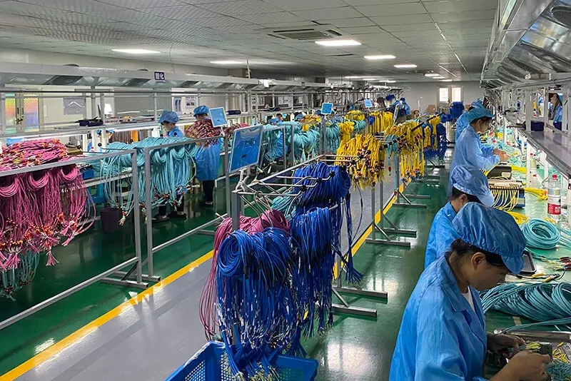
For production orders, request cable-level test records tied to a serial number, batch number, or other traceable identifier. A generic certificate stating that a product “passed testing” offers little help when a field issue must be investigated. Our overview of the MPO patch cord manufacturing process explains how assembly, polishing, inspection, and optical testing fit together during production.
Step 6: Specify Installation and Identification Details
Optical compatibility is only part of the order. The cable must also survive its route and remain understandable after installation.
Confirm the overall length, measurement reference points, tolerance, minimum bend radius, pulling method, and any required pulling eye. For breakout assemblies, specify the fanout length, branch protection, and branch sequence. In crowded racks, boot length and connector access may matter as much as the cable diameter.
The jacket requirement should reflect the installation environment and local code. Riser, plenum, and low-smoke zero-halogen designations are not universal substitutes for one another. State the project location, pathway type, indoor or outdoor exposure, temperature range, and applicable fire or environmental requirement.
Labels should correspond to the fiber map and installation drawing. Define label text, position, reading direction, barcode or serial-number requirements, and packaging sequence. For multi-cabinet deployments, cabinet-based kits can reduce sorting time and installation mistakes.
Supplier and Batch-Quality Checklist
A technically correct sample does not guarantee consistent bulk production. Before approving an MPO patch cord supplier for a project or OEM program, confirm how the approved design will be controlled through repeat orders.
| Check | What the buyer should request |
|---|---|
| Specification review | Written confirmation of connector types, fiber count, polarity, pin condition, end faces, length, jacket, and application |
| Drawing and fiber map | Controlled drawing with revision number and Connector A-to-B mapping |
| Sample approval | A production-intent sample made with the proposed materials and test process |
| Optical test records | Per-fiber insertion-loss results plus the agreed return-loss, polarity, length, and inspection records |
| Material control | Confirmed connector, ferrule, fiber, cable, fanout, boot, and jacket specifications |
| Repeat-order control | Part number, drawing revision, approved sample, test limits, and change-notification procedure |
| OEM requirements | Label artwork, cable marking, bag label, carton mark, barcode, and packing quantity |
| Delivery plan | Sample date, first-article approval, production milestones, inspection point, and shipment schedule |
Any substitution that can affect optical or mechanical performance should require buyer approval. This is particularly important when a project will be installed in phases or reordered over several years. If the cable will be sold under your own brand or supplied as part of a larger system, define the private label, packaging, documentation, and change-control requirements as part of the OEM/ODM fiber optic service scope.
A Copy-and-Paste MPO/MTP RFQ Template
The following checklist can be added to a request for quotation or cable drawing:
Application and equipment interface:
Network standard / transceiver model:
Cable architecture: MPO-MPO trunk / MPO-LC breakout / other
Connector A:
Connector B:
Fiber count and fiber mapping:
Fiber type:
Polarity method:
Key orientation:
Pinned or unpinned configuration:
End face for each connector:
Overall length and tolerance:
Breakout branch length and labels:
Jacket and installation environment:
Maximum insertion loss:
Minimum return loss:
Test wavelengths and test method:
End-face inspection requirement:
Test report and traceability requirement:
Labeling and packaging:
Sample quantity / order quantity:
Required delivery date:
If any field is unknown, flag it for engineering review instead of allowing the supplier to assume a default. A short clarification before production is far less expensive than repolarizing, relabeling, or replacing cables during deployment.
How YingFeng Supports Project-Based MPO/MTP Cable Production
YingFeng supports MPO/MTP cable projects from specification review and sample confirmation through batch production, testing, labeling, and delivery. Available configurations include MPO-to-MPO trunks, MPO-to-LC or MPO-to-SC breakout cables, conversion assemblies, single-mode and multimode fibers, Type A/B/C polarity, and project-specific lengths and packaging.
Before production, our team can review the equipment interface, fiber count, polarity, connector pin configuration, cable drawing, test limits, and application environment. Pre-production samples can then be checked against the approved specification before a bulk order is released.
During production, optical performance, polarity, end-face condition, labels, and packaging should be controlled against the confirmed drawing and order requirements. Maintaining the same part number, drawing revision, approved materials, and test criteria also makes repeat orders easier to verify.
Build the Specification Around the Complete Link
Reliable MPO/MTP cabling begins with a channel design, not a product name. Define the equipment interfaces first, then select the architecture, fiber count, fiber type, polarity, pin configuration, end face, and optical limits that make the complete link work.
Finally, document installation details and batch-quality controls with the same precision as the optical specification. When the RFQ, fiber map, sample, and test report all describe the same assembly, project teams can deploy high-density fiber links with fewer compatibility surprises and a much clearer path for future expansion.
Need help confirming an MPO/MTP cable specification? Explore YingFeng’s custom MPO/MTP patch cable range or send your drawing and project requirements to our team for specification review and quotation support.