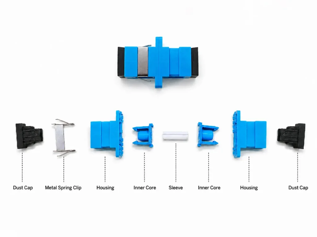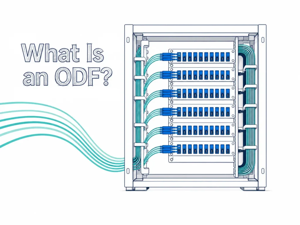

If you’ve ever been inside a data center, a server room, or even just looked closely at network equipment, you’ve probably seen this. Rows of devices connected by thin, colorful cables, each with a small connector plugged neatly into a port. They look a bit like Ethernet cables, but more precise, more delicate.
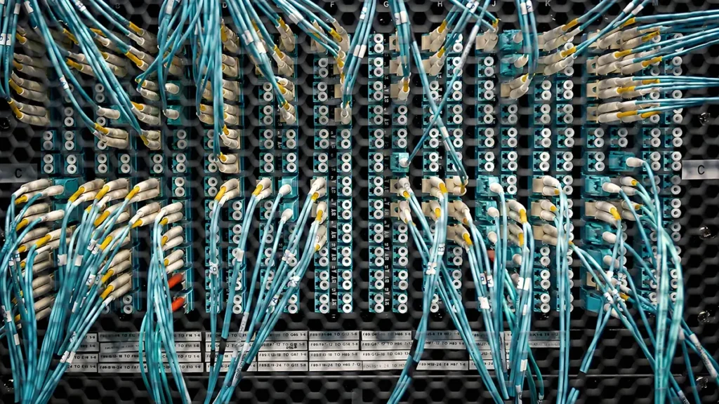
Those are what we call fiber optic patch cords. Some people also call them fiber jumpers, but in most cases, patch cord is the more common term.
When I first got into this industry, I didn’t think much of them. They looked simple enough. But the more I worked with them, the more I realized—there’s actually quite a lot going on behind something that looks so basic.
So this article is partly for beginners who want to understand patch cords from scratch, and partly for myself—to organize the knowledge in one place. Because honestly, some of these details are easy to forget.
If you already know the basics and want to know more about buying, you can skip ahead later. Click Here to jump.
But if you’re new, it’s worth going through step by step.
TABLE OF CONTENTS
So What Exactly Is a Fiber Optic Patch Cord?
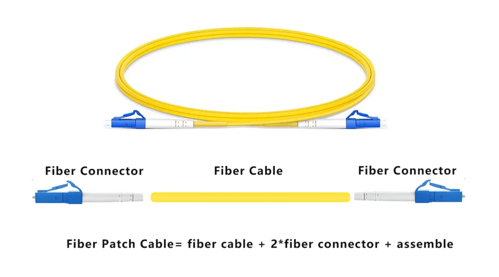
If I had to explain it in one sentence, I’d say: a fiber optic patch cord is simply a fiber cable with connectors on both ends, used to connect two devices and transmit optical signals between them.
That’s the simplest way to understand it. You plug one end into a switch or ODF, the other into another device, and the signal travels through the fiber in between. It’s essentially the “last meter” or “last few meters” connection in most fiber optic systems.
If you want a slightly more formal definition, it’s a terminated fiber assembly designed for flexible and quick optical interconnection. But in real life, thinking of it as a “bridge” between devices is much more practical.
Since it’s basically made up of a cable and two connectors, the easiest way to understand it is to break those two parts apart and look at them separately.
What’s Inside the Cable: Structure and Common Diameters

The cable part of a fiber optic patch cord is actually much simpler than a full fiber optic cable, but there are still a few important details worth understanding.
At the center, there is the optical fiber itself, which is made of a glass core and cladding. This is where the light travels. Around it, there’s usually a buffer coating that protects the fiber from mechanical stress, and then an outer jacket that provides physical protection and flexibility.
Compared to outdoor fiber cables with multiple layers, strength members, and waterproof structures, patch cords are designed for flexibility and ease of use, so the structure is intentionally kept simpler.
One thing that often gets overlooked is the diameter of the patch cord, which actually matters quite a bit depending on where and how it’s used. The most common diameters you’ll see are:
- 0.9mm → very thin, often used inside equipment or for pigtails
- 1.2mm / 1.6mm → lightweight, flexible applications
- 2.0mm → very common for indoor patch cords
- 3.0mm → thicker, more robust, better for frequent handling
In practice, 2.0mm and 3.0mm are the most widely used. The thinner ones save space and are easier to manage in high-density environments, while thicker cables provide better mechanical strength and durability.
So even though it looks like “just a cable,” the structure and diameter already affect performance, durability, and application scenarios.
Single Mode vs Multimode — Not Just a Label, But a Fundamental Difference
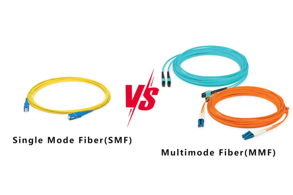
When people talk about fiber patch cords, the first and most important distinction is always single mode vs multimode, and this is not just a naming difference—it’s a completely different transmission principle.
In single mode fiber, light travels along one single path through the core. Because there’s only one propagation mode, there’s very little signal dispersion, which makes it ideal for long-distance transmission. That’s why single mode fiber is used in telecom networks, long-distance links, and FTTH deployments.
Multimode fiber, on the other hand, allows multiple light paths (modes) to propagate at the same time. This makes it easier to couple light into the fiber, but it also introduces modal dispersion, which limits the transmission distance. That’s why multimode fiber is mainly used for short-distance, high-speed communication, especially inside data centers.
If we go a bit deeper into common types, single mode fibers typically include:
- G.652D → standard single mode fiber
- G.657A1 / G.657A2 → bend-insensitive fibers
In real-world projects today, G.657A1 and G.657A2 are becoming increasingly common because they can handle tighter bending without significant signal loss, which makes installation much easier.
On the multimode side, you’ll usually see:
- OM1 / OM2 → older generations
- OM3 / OM4 → widely used in modern data centers
- OM5 → newer, designed for wavelength division multiplexing
If you want a more detailed breakdown of how these differ in performance and use cases, it’s worth reading a dedicated comparison like Single Mode vs Multimode fiber. Here we just focus on the key idea: single mode goes far, multimode goes fast over short distances.
Fiber Colors — There’s a System Behind It
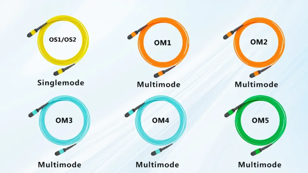
At first glance, patch cords just look colorful, but those colors actually follow industry conventions.
For example, single mode patch cords are almost always yellow, which makes them easy to identify in a rack. Multimode fibers use different colors depending on their type:
- OM1 / OM2 → usually orange
- OM3 / OM4 → typically aqua
- OM5 → often lime green
This color coding is not random—it follows standards like TIA/EIA, and it helps technicians quickly identify fiber types without checking labels.
If you want to understand the full system, including connectors, jackets, and international standards, you can refer to this guide:
👉 Fiber Optic Color Code Explained: A Complete Guide with TIA/EIA Standards
In practice, once you get used to it, you’ll find yourself recognizing fiber types almost instantly just by color.
Simplex, Duplex, and More — How Many Fibers Are Inside?
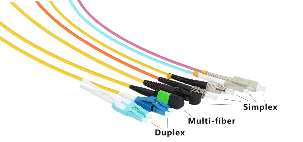
Another thing you’ll notice is that not all patch cords look the same structurally. Some are a single strand, while others are two fibers bonded together.
This refers to the number of fibers inside the cable:
- Simplex → one fiber, used for single-direction transmission
- Duplex → two fibers, used for bidirectional communication (very common)
- Multi-fiber → multiple fibers, often used with MPO connectors
Most network equipment requires both sending and receiving signals, which is why duplex patch cords are the standard choice in many applications.
The Outer Jacket — Small Detail, Real Impact
The outer jacket of a patch cord might not seem important at first, but it plays a critical role in safety and application suitability.
Today, most indoor patch cords use LSZH (Low Smoke Zero Halogen) material. The main advantage is that in case of fire, it produces very little smoke and no toxic halogens, which makes it much safer for enclosed environments like data centers, offices, and buildings.
In many projects, LSZH is not just preferred—it’s required by regulation.
Now Let’s Talk About Fiber Connectors — The Part That Really Matters
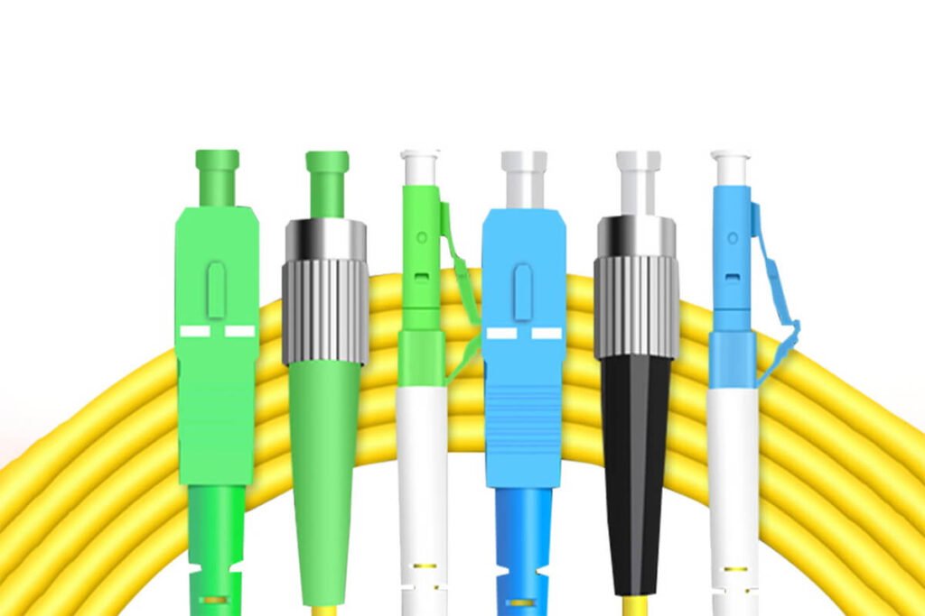
Once you understand the cable, the next step is the fiber connectors. In many real-world situations, if something goes wrong, it’s not because of the fiber itself, but because of the connector—either the wrong type, poor quality, or improper matching.
There are quite a few connector types in the market, but they don’t all have equal importance.
In practical applications, three connector types dominate:
- LC (Lucent Connector) → compact, high-density, widely used in modern networks
- SC (Subscriber Connector) → larger, push-pull design, still very common
- MPO/MTP → multi-fiber connectors, essential for high-density data center applications
LC connectors are probably the most common today, especially in switches and high-density panels. SC connectors, although older, are still widely used in telecom and FTTH environments because of their simple and reliable structure. MPO connectors are a different category altogether—they handle multiple fibers in a single connector, making them critical for high-speed backbone connections in data centers.
Besides these, there are also other types like:
- FC → threaded, often used in testing environments
- ST → bayonet-style, older installations
- E2000, MU, MTRJ → more specialized or less common
You don’t need to remember all of them in detail, but it helps to recognize them when you see them.
UPC vs APC — A Small Detail That Makes a Big Difference
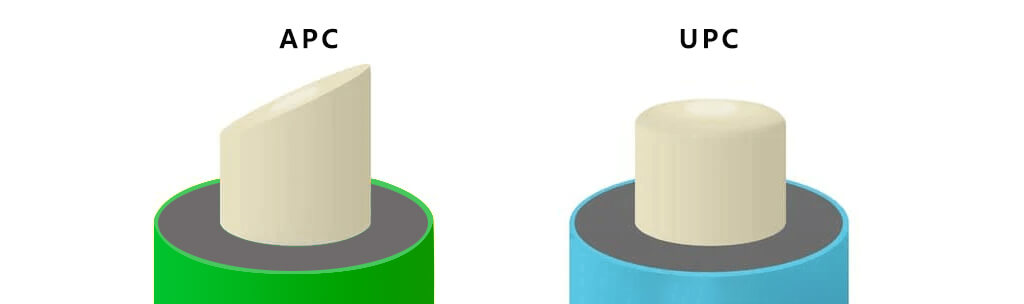
Another important aspect of connectors is the polish type, mainly UPC and APC.
The easiest way to tell them apart is by color:
- Blue → UPC
- Green → APC
Structurally, UPC connectors have a flat end face, while APC connectors have an angled end face (usually 8 degrees). This angled design reduces back reflection, which improves return loss performance.
In high-performance or long-distance systems, APC connectors are often preferred.
One thing to remember is that UPC and APC should never be mixed, because the physical mismatch can cause signal loss and poor performance.
Putting It All Together — How a Patch Cord Is Fully Defined
At this point, we can combine everything we’ve discussed into one complete picture.
A fiber optic patch cord is not just a “cable”—it’s defined by a set of parameters that together determine exactly what it is and how it performs.
A typical specification includes:
- Fiber mode (single mode or multimode)
- Fiber type (e.g., G657A1 or OM4)
- Core size (e.g., 9/125 or 50/125)
- Number of fibers (simplex or duplex)
- Connector types on both ends
- Polish type (UPC or APC)
- Cable diameter (2.0mm, 3.0mm, etc.)
- Length (1m, 3m, etc.)
- Jacket type (LSZH, etc.)
For example: G657A1 9/125 Duplex LC/UPC–LC/UPC 2.0mm 3m LSZH
Once you understand each part of this specification, you can fully identify what that patch cord is and whether it fits your application. In other words, every parameter matters, and together they define a unique product.
A Few Practical Things People Often Overlook
Before moving on to the buying guide, there are a few practical points that are easy to ignore, especially if you’re new.
First, bend radius. Fiber is not as flexible as it looks, and bending it too tightly can increase signal loss or even damage the fiber.
Second, connector cleanliness. Even microscopic dust can affect optical performance. In many cases, signal issues are caused by dirty connectors rather than faulty cables.
And finally, compatibility. Using the wrong connector type or mixing APC and UPC can lead to unexpected problems.
These details might seem small, but in real-world applications, they make a big difference.
If You Just Wanted the Basics, This Is Enough
If your goal was simply to understand what fiber optic patch cords are, you should now have a solid foundation.
But if you’re planning to actually buy them, things become more practical—and more complicated. Specifications, quality differences, pricing, and application requirements all come into play.
So in the next part, we’ll shift focus to a more real-world question:
How do you choose the right fiber optic patch cord for your project?
Final Thoughts
As you’ve seen throughout this guide, there’s actually a lot behind it—fiber types, connector standards, cable structures, and specifications that all affect performance in real-world applications.
The good news is that once you understand these basics, everything becomes much easier. You’ll be able to read specifications confidently, avoid common mistakes, and choose the right patch cord for your specific use case.
If you’re planning to move from understanding to actual purchasing, the next step is learning how to evaluate suppliers, compare pricing, and avoid sourcing risks.
You can continue reading here: How to Choose a Fiber Optic Patch Cord Manufacturer (2026 Guide)
Because in practice, knowing the product is only half the job—choosing the right supplier is what really determines the final result.