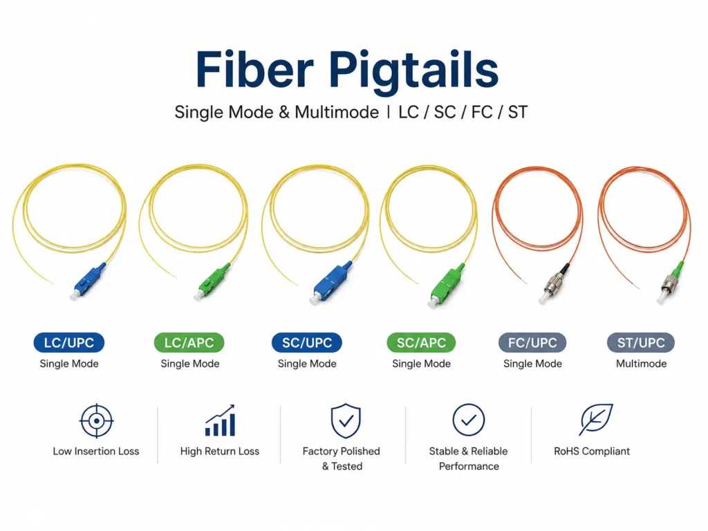
In the world of optical communication, fiber optic connectors are among the most commonly used components people encounter. Many already know that the biggest difference between APC and UPC connectors is the polishing angle:
- APC connectors use an 8-degree angled polish
- UPC connectors use a straight polished end face
This seemingly small difference is what allows APC connectors to achieve much higher return loss performance than UPC connectors. Many people only know the conclusion, but not the principle behind it — why do APC fiber optic connectors need to be polished at an 8-degree angle?
In reality, the small green APC connector involves a surprising amount of optical engineering. Next, I’m going to reveal the real optical principle behind why APC connectors use an 8-degree polishing angle. Trust me — even if you’re not an optical engineer, you’ll still be able to understand it.
TABLE OF CONTENTS
The Short Scientific Explanation
APC fiber connectors are polished at an 8-degree angle because the angled end face redirects Fresnel reflections away from the fiber core, preventing reflected light from coupling back into the optical path.
From a geometric optics perspective, the reflected beam exits at an angle larger than the fiber’s numerical aperture acceptance angle, meaning it can no longer efficiently re-enter the core. From a wave optics perspective, the angular mismatch between the reflected Gaussian beam and the forward-propagating optical mode dramatically reduces coupling efficiency.
The 8-degree design is not arbitrary. It represents a practical engineering balance between high return loss, low insertion loss, manufacturing tolerance, and long-term connector reliability. This is why 8° APC connectors are widely used in FTTH, PON, CATV, RF over Fiber, and DWDM systems where back reflection must be minimized.
First, What Is Actually Being Reflected?
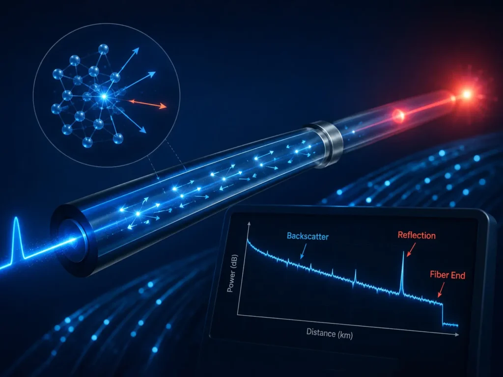
To understand APC connectors, we first need to understand what optical engineers are trying to control in the first place: reflected light.
Whenever light moves from one material to another, a small portion of that light reflects backward. This phenomenon is called Fresnel reflection. You can observe the same effect when looking at a glass window or the surface of water — some light passes through, while some bounces back toward you.
Exactly the same thing happens inside a fiber optic connector.
When an optical signal reaches the connector end face, most of the light continues forward into the next fiber, but a small amount reflects backward toward the laser source. In modern optical systems, especially those using high-speed lasers or analog optical transmission, this reflected light can create serious problems. It may destabilize the laser, increase optical noise, reduce signal quality, and affect transmission performance.
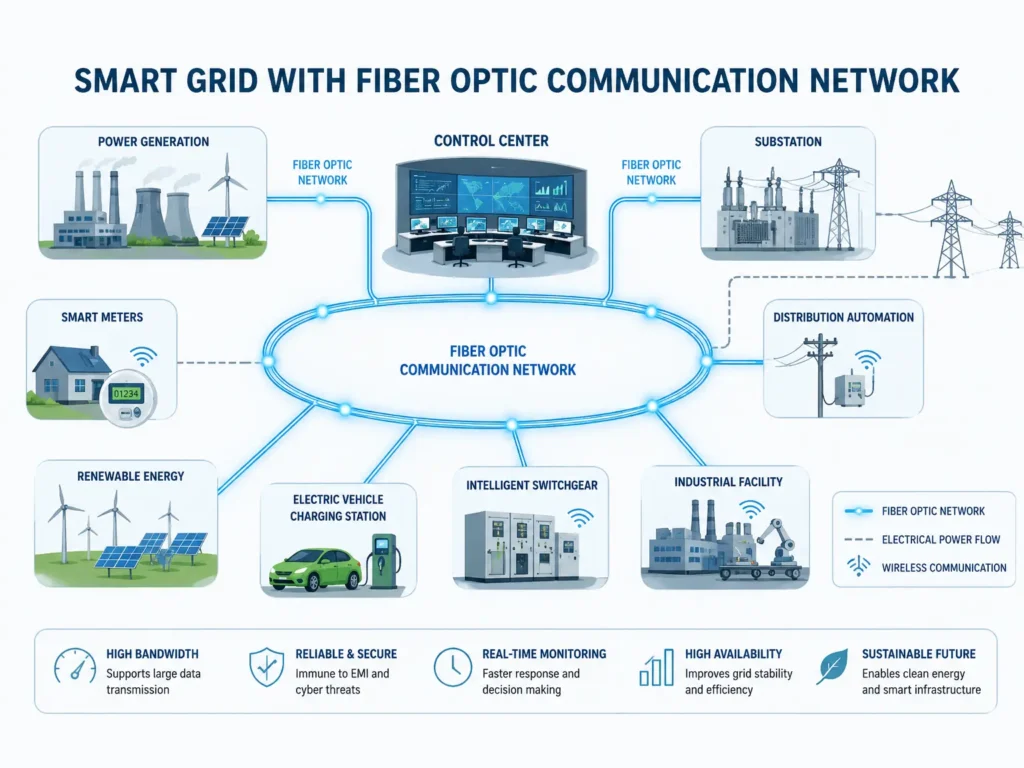
This is particularly important in systems such as:
- PON networks
- CATV optical
- transmission
- DWDM systems
These systems are highly sensitive to optical reflection.Reflected light can interfere with the laser, introduce noise, destabilize transmission, and reduce signal quality.
This means the goal of APC is not actually to eliminate reflection entirely. That would be nearly impossible. Instead, the real objective is much smarter:
Prevent the reflected light from coupling back into the fiber core.
That single idea is the foundation of APC connector design.

Why UPC Connectors Still Have Reflection
Before APC became common, most fiber connectors used flat or slightly curved physical contact polishing methods. UPC connectors already improved dramatically compared to older flat-polish connectors because the fiber ends physically touch each other, reducing the tiny air gap between the ferrules.
Without that air gap, reflection is reduced significantly. This is why UPC connectors can typically achieve return loss values around 50 dB.
However, UPC still has one important limitation: the connector end face remains essentially perpendicular to the fiber axis. Even though the surface is polished extremely smoothly, reflected light still travels almost directly backward along the same optical path.
You can imagine shining a flashlight directly at a mirror. The reflected light comes straight back toward you. UPC connectors behave similarly. The reflected signal still has a relatively high probability of re-entering the fiber core.
And that is exactly what APC was designed to solve.
The Core Principle of APC: Redirecting the Reflection
APC stands for Angled Physical Contact. The key difference is simple: instead of polishing the connector end face perpendicular to the fiber axis, the ferrule is polished at an angle — typically 8 degrees.
That angled surface changes the direction of reflected light. Rather than bouncing straight back into the core, the reflected signal is deflected sideways into the cladding area. Once the reflected angle becomes larger than the fiber’s acceptable receiving angle, the light can no longer efficiently couple back into the core.
This is the real reason APC connectors achieve much higher return loss.
A useful way to think about this is to imagine the fiber core as a narrow tunnel. Light entering at the correct angle can travel through the tunnel successfully. But if the angle becomes too large, the light simply crashes into the wall and escapes instead of continuing forward.
The same thing happens to reflected light inside an APC connector. The angled polish intentionally pushes the reflected beam outside the fiber’s acceptable coupling range.
As a result, APC connectors can often achieve return loss values above 60 dB, significantly better than UPC connectors.
Understanding Numerical Aperture Without Complicated Math
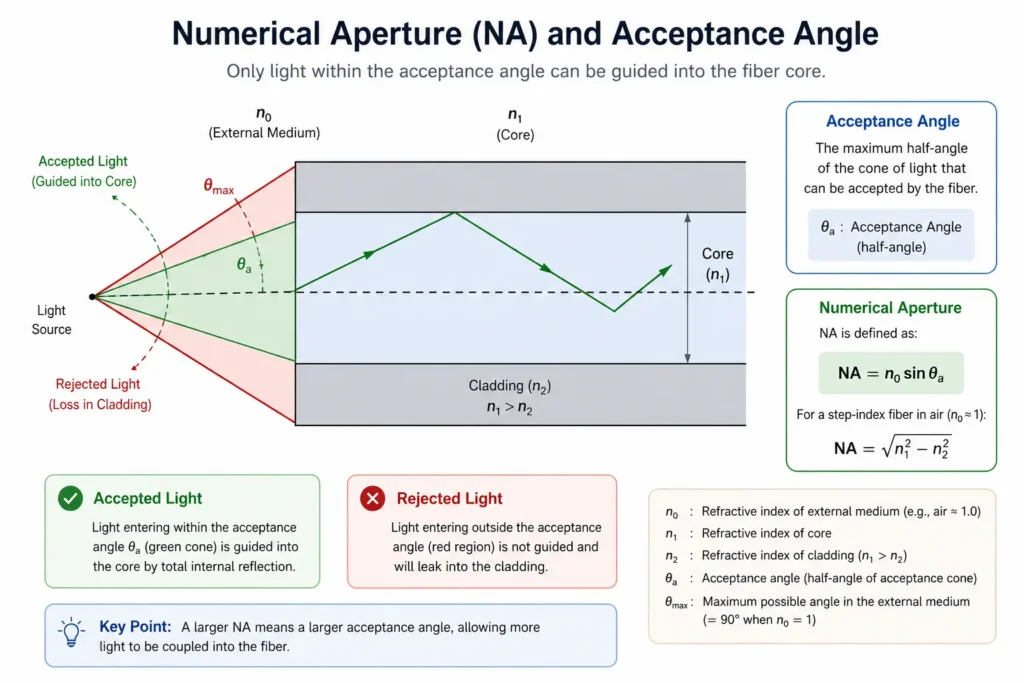
At this point, many articles suddenly become filled with formulas and optical equations. But the basic idea is actually simpler than it sounds.
Every optical fiber has a limited acceptance angle. In other words, the fiber only accepts light entering within a certain angular range. This range is determined by the fiber’s Numerical Aperture, commonly called NA.
If reflected light returns within that acceptable angle, part of the signal can re-enter the core. But if the reflected beam is pushed outside that range, coupling efficiency drops dramatically.
The 8-degree APC angle is carefully designed so that reflected light exits beyond the effective acceptance angle of the fiber. Once that happens, the reflected signal can no longer efficiently travel backward through the system.
This is why APC connectors work so effectively across different wavelengths and communication systems.
Why Exactly 8 Degrees?
At first glance, it might seem logical to assume that a larger angle would always be better. If angled polishing redirects reflection, then why not use 12 degrees or even 15 degrees?
The answer is that optical connector design is always a balance between multiple competing factors.
If the polishing angle is too small, such as 4 or 5 degrees, some reflected light can still partially couple back into the fiber core. Return loss improves, but not enough for demanding optical systems.
However, if the angle becomes too large, another problem appears: insertion loss begins to increase.
When two fibers connect together, their optical axes must remain aligned as precisely as possible. Excessive polishing angles introduce angular mismatch between the fiber cores, making efficient optical coupling more difficult. In simple terms, the light starts missing its target.
Larger angles also create additional manufacturing challenges. Connector alignment becomes more sensitive, polishing tolerances become tighter, and contamination or small defects can have a greater impact on performance.
After extensive industry testing and optimization, engineers found that around 8 degrees provides the best overall balance between:
- high return loss
- low insertion loss
- manufacturing tolerance
- long-term reliability
This is why 8 degrees eventually became the industry standard for APC connectors.
The Deeper Explanation: Wave Optics and Gaussian Mode Coupling

The explanation so far mainly comes from geometric optics, where light is treated like straight rays traveling through space. But optical fibers, especially single-mode fibers, are more accurately described using wave optics.
Inside a single-mode fiber, light propagates as a Gaussian optical mode rather than a simple straight beam. This introduces another important effect known as angular mode mismatch.
Even if a small portion of reflected light still manages to return toward the fiber core, the reflected optical mode no longer perfectly matches the forward-propagating mode because the angle has changed. This mismatch dramatically reduces coupling efficiency.
In other words, APC connectors improve return loss in two ways simultaneously:
- They physically redirect reflected light away from the core.
- They reduce optical mode coupling efficiency through angular mismatch.
This second mechanism is one of the deeper reasons APC connectors perform so well in high-performance optical systems.
Why the Return Loss Curve Changes at 1310nm and 1550nm

If you look at the return loss graph for different polishing angles, you’ll notice that 1310nm and 1550nm wavelengths do not produce exactly the same curve.
This mainly relates to Mode Field Diameter (MFD).
For example, Corning SMF-28 fiber has a smaller mode field diameter at 1310nm and a larger mode field diameter at 1550nm. A larger optical mode tends to be slightly more sensitive to angular misalignment, which affects coupling efficiency differently at different wavelengths.
However, the overall trend remains the same: as the polishing angle increases, return loss improves dramatically because reflected light becomes increasingly difficult to couple back into the fiber core.
This is also why APC connectors work effectively across multiple communication wavelengths without requiring different polishing angles for different systems.
Why APC and UPC Should Never Be Mixed
Because APC and UPC connectors use different end-face geometries, they should never be directly connected together.
When an angled APC connector mates with a flat UPC connector, the fiber cores do not physically align correctly. This can cause severe insertion loss, poor return loss, and even permanent end-face damage.
This is why APC connectors are typically color-coded green, while UPC connectors are usually blue. The color difference acts as a quick visual warning to prevent accidental mismatching.
Final Thoughts
At first glance, the 8-degree angle on an APC connector may seem like a small mechanical detail. But behind that tiny angled surface is a carefully optimized optical solution developed through decades of engineering experience.
The 8-degree APC polish is not arbitrary. It represents a balance between reflection control, mode coupling behavior, insertion loss, manufacturing tolerance, and long-term reliability. By redirecting reflected light beyond the fiber’s acceptable coupling range, APC connectors achieve the high return loss performance required in modern optical communication systems.
So the next time you see a small green APC connector, you’ll know that the famous 8-degree angle is far more than a manufacturing choice — it is a precise optical engineering solution to one of fiber communication’s most important challenges.