
TABLE OF CONTENTS
How 400G Ethernet Works
A 400G port does not push one 400 Gb/s signal down one strand of glass. The data is split into parallel lanes, and each lane is encoded and protected by forward error correction (FEC).
- Line rate vs. data rate. The MAC rate is 400 Gb/s. After 256b/257b encoding and Reed-Solomon RS(544,514) FEC are added, the 400GBASE-R signal runs at a nominal 425 Gb/s. The extra 25 Gb/s is overhead, not usable bandwidth.
- Lanes. Different 400G optics use different lane plans. Some use eight lanes of 50G PAM4, others four lanes of 100G PAM4. The lanes are carried either on separate fibers (parallel optics) or on separate wavelengths in one fiber pair (WDM optics).
- PAM4. The short-reach 400G optics in use today use PAM4 modulation, which carries two bits per symbol on four signal levels. That leaves less margin than older NRZ signaling, so FEC is always on. It is also why an extra dirty connector or poor mating shows up faster at 400G than it did at 10G.
The module housing is a separate choice from the optical interface. QSFP-DD and OSFP are the two main 400G form factors, and QSFP112 appears on some newer network adapters. The same optical interface, DR4 for example, can come in more than one form factor. So when you order, match three things: the switch or NIC cage, the form factor, and the optical interface.
Where 400G Fits Today: 100G, 400G and 800G
400G sits between the 100G links that still connect many servers and the 800G links now appearing in new AI clusters.
- Spine and aggregation. A common upgrade path is a 400G spine that keeps existing 100G leaf switches and servers, using 400G-to-4×100G breakout (covered below).
- AI clusters. In an NVIDIA DGX H100 system, the compute network runs through eight ConnectX-7 adapters at up to 400 Gb/s each, exposed through four OSFP ports. NVIDIA’s Quantum-2 InfiniBand and Spectrum-4 SN5600 switches house two 400 Gb/s ports in each twin-port OSFP cage. 800 Gb/s adapters such as ConnectX-8 have now arrived, but a large installed base still runs on 400G ports. You can read more about how GPU clusters use these links in our GPU networking guide.
- Data center interconnect. 400ZR is a coherent DWDM interface defined by the OIF for amplified point-to-point links of up to 120 km. It is a different technology from the short-reach optics we are discussing here, so keep it out of your in-building cabling plan.

400G Optics and the Fiber Each One Needs
This is the decision that shapes your cabling, so we have put the IEEE 400G interfaces you are most likely to meet inside a data center side by side.
| 400G interface | IEEE standard | Fiber and reach | Fibers and connector | Max channel insertion loss |
|---|---|---|---|---|
| 400GBASE-SR8 | 802.3cm (2020) | OM3 70 m, OM4 100 m | 16 fibers, MPO | 1.8 dB (OM3), 1.9 dB (OM4) |
| 400GBASE-SR4.2 | 802.3cm | OM3 70 m, OM4 100 m, OM5 150 m | 8 fibers, MPO (bidirectional, 850/910 nm) | 1.7 dB (OM3), 1.8 dB (OM4), 2.0 dB (OM5) |
| 400GBASE-DR4 | 802.3bs (2017) | Single-mode, 500 m | 8 fibers, MPO | 3.0 dB |
| 400GBASE-FR4 | 802.3cu (2021) | Single-mode, 2 km | Duplex LC, 4 CWDM wavelengths | 4.0 dB |
| 400GBASE-LR4-6 | 802.3cu | Single-mode, 6 km | Duplex LC | 6.3 dB |

We would take three things from this table:
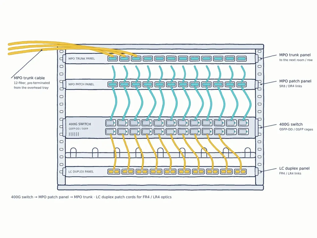
- Parallel optics use MPO; WDM optics use duplex LC. SR8, SR4.2 and DR4 send each lane on its own fibers, so they need MPO/MTP connectors. FR4 and LR4-6 combine four wavelengths onto a single fiber pair, so a standard duplex LC patch cord works.
- Count the fibers, not only the connector. SR8 uses 16 fibers, so it needs a 16-fiber MPO (usually MPO-16). A 12-fiber MPO will not work. DR4 and SR4.2 use eight fibers. In a 12-fiber MPO, four transmit and four receive fibers are active and the middle four positions stay empty.
- Single-mode MPO is usually APC. 400G DR4 modules from major vendors specify MPO-12/APC. Cisco lists “MPO-12 SMF APC” for its QSFP-400G-DR4, and NVIDIA’s DR4 optics use an 8-degree APC end face to deflect back reflections. APC and UPC connectors must never be mated; see our APC vs UPC guide.
For a general guide to matching patch cords with transceiver ports, see how to choose fiber patch cords for optical modules. For MPO basics, read the MPO connector guide.
400G Breakout: What Works and What Doesn't
Breakout lets one 400G port serve several lower-speed ports. It is one of the most useful features of 400G and also one of the most common sources of trouble.
What works. A DR4 port carries four independent 100G lanes on four fiber pairs, so it can split into four 100G single-wavelength links. Cisco, for example, lists its QSFP-400G-DR4 as supporting “4x100G-DR1/FR1 and 2x200G-DR2 breakout.” Cable it with an MPO-12/APC to four LC duplex breakout cable, or run an MPO trunk to a patch panel that fans out to LC ports.
What doesn’t work.
- FR4 and LR4 can’t be broken out passively. Their four lanes share one fiber pair on different wavelengths, so there is nothing to split with a fan-out cable.
- DR4 lanes do not talk to 100G-LR4. A 100G-LR4 optic also multiplexes four wavelengths onto one pair. It is not the single-wavelength 100G interface a DR4 lane expects. Match the far end to DR1/FR1/LR1-class optics that your switch vendor supports.
- Breakout is a port setting as well as a cable. The switch port must be configured for breakout mode. If only two of the four 100G links come up, check the port mode first. Then check each fiber pair in turn for polarity, a dirty end face or a damaged fiber.
Keep it tidy. A rack full of breakout legs gets messy fast. Choose leg lengths that suit the rack instead of one default length. If you have many breakouts, consider running MPO trunks to a patch panel and patching the LC side locally. Every extra mated pair uses part of the loss budget, so plan it on paper first.
For example, we supply an MPO-8 to 4×LC breakout cable, single-mode, APC to UPC.

Physical-Layer Checklist Before You Turn Up 400G
In our experience, most 400G link problems in a new build come from the passive layer. Go through these points before you power up the optics.
- Fiber count and MPO size. Match 8-fiber interfaces (DR4, SR4.2) and 16-fiber interfaces (SR8, and the 800G interfaces below) to the right MPO. Remember that “MPO-12” in a DR4 link means eight active fibers.
- Fiber type and end face. Use OS2 single-mode with APC for DR4, OM3/OM4/OM5 multimode for SR8 and SR4.2, and single-mode duplex LC for FR4/LR4-6. Don’t mix APC and UPC anywhere in the channel.
- Pinned vs. unpinned. MPO connectors mate one pinned (male) with one unpinned (female). Transceiver ports usually have pins, so the patch cord ends that plug into them should be unpinned. Check this for every trunk, adapter and patch cord.
- Polarity method. TIA defines three polarity methods: A, B and C. They are not compatible with one another. Pick one method for the whole channel and make sure the trunks, adapters and patch cords all follow it.
- Loss budget. The IEEE limits are tight. A DR4 channel allows 3.0 dB in total, of which 2.75 dB is allocated to connections and splices. SR8 over OM4 allows only 1.9 dB for the whole channel. Every patch panel adds mated pairs, which is why low-loss MPO/MTP cords matter in structured 400G cabling. Add up your planned connections against the channel limit before you order.
- Inspect and clean. IEC 61300-3-35 sets out how to inspect end faces for contamination and defects. Inspect, clean if needed, then inspect again. The standard also notes that visual inspection does not replace measuring insertion loss and return loss, so test the link too.
- Label everything. Label both ends of every trunk and breakout leg with port, fiber count and polarity. The next person who has to troubleshoot a lane at 2 a.m. will thank you.
For a step-by-step ordering guide, see how to specify MPO/MTP patch cords.
Planning Your 400G Cabling for 800G
Few teams install 400G without asking us about 800G. The answer depends on which path the 800G optics take.
- MPO-12/APC can carry over. NVIDIA’s 800G twin-port OSFP transceiver for switches is effectively two 400G DR4 engines in one module, with two MPO-12/APC connectors. Its ConnectX-8 800G DR4 optics also use MPO-12/APC, with four 200G lanes. A well-built MPO-12/APC single-mode plant can therefore serve these parts. Check the module’s reach and loss specifications first, because higher lane rates can come with different limits.
- 16-fiber interfaces need 16 fibers. IEEE 802.3df (2024) defines 800GBASE-DR8 as 16 single-mode fibers to 500 m (3.0 dB channel) and 800GBASE-SR8 as 16 multimode fibers to 100 m on OM4 (1.8 dB channel). If your trunks only carry eight usable fibers per link, these interfaces will need new cabling.
- What to do now. Choose trunk fiber counts that leave room to grow, stay on OS2 single-mode for anything beyond a row, standardize on one polarity method and keep a record of measured link loss. That record will tell you whether an 800G upgrade can reuse the plant or needs new cords.
Sourcing 400G Passive Connectivity from YingFeng
YingFeng has 25+ years of fiber optic manufacturing experience, with manufacturing roots dating to 1982, and two manufacturing bases in Ningbo and Dongguan. For 400G and 800G projects we supply:
- MPO/MTP patch cords in 8-, 12-, 16- and 24-fiber configurations, including low-loss versions. They are produced in a cleanroom, with a monthly capacity of 300,000 assemblies.
- LC duplex patch cords for FR4 and LR4-6 links, and fiber optic adapters for patch panels.
- Connector kits and individual components for cable assembly houses, with custom tooling available for customer-specific parts.
We offer OEM/ODM service, and samples are available on request. Send us your transceiver models and port count, and we will suggest a matching patch cord and breakout list.
FAQ
What is 400 Gbps Ethernet?
400 Gbps Ethernet (400GbE) is the IEEE Ethernet rate of 400 gigabits per second, first standardized in IEEE 802.3bs-2017. It carries data over 4 or 8 PAM4 lanes, on multimode or single-mode fiber depending on the optic.
Does 400G use single-mode or multimode fiber?
Both. SR8 and SR4.2 run on OM3/OM4/OM5 multimode fiber for up to 70–150 m. DR4, FR4 and LR4-6 run on single-mode fiber for 500 m, 2 km and 6 km respectively.
What connector does 400G DR4 use?
DR4 uses an MPO connector with eight active single-mode fibers, typically MPO-12/APC.
Can a 400G port break out to 4×100G?
Yes, if it is a DR4 port and the switch supports breakout mode. Each lane links to a single-wavelength 100G optic such as DR1 or FR1. FR4 and LR4 optics can’t be broken out with passive cables.
Is 400G being replaced by 800G?
800G is arriving in new AI clusters, but 400G ports remain widely deployed. Much 800G equipment still divides into 2×400G. Cabling built on MPO-12/APC single-mode can often carry over, while 16-fiber interfaces such as 800GBASE-DR8 need 16-fiber links.
External references
- IEEE P802.3bs Task Force: https://www.ieee802.org/3/bs/
- TIA FOTC, IEEE 802.3 application summaries: https://www.tiafotc.org/ieee-802-3-ethernet-standards-update/
- OIF 400ZR Implementation Agreement: https://www.oiforum.com/