MPO patch cords are not simply standard fiber optic patch cords with more fibers inside. A reliable MPO fiber cable assembly depends on the MT ferrule, multi-fiber alignment, correct polarity, controlled polishing, and full-channel testing. When one connector carries 8, 12, 16, 24, or more fibers, a small defect on one channel can affect the whole connector.
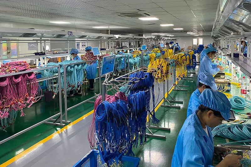
In factory production, an MPO patch cord moves through a controlled workflow that starts with material confirmation and cable cutting, then continues through MT ferrule assembly, polishing, 3D inspection, IL/RL testing, labeling, and packaging.
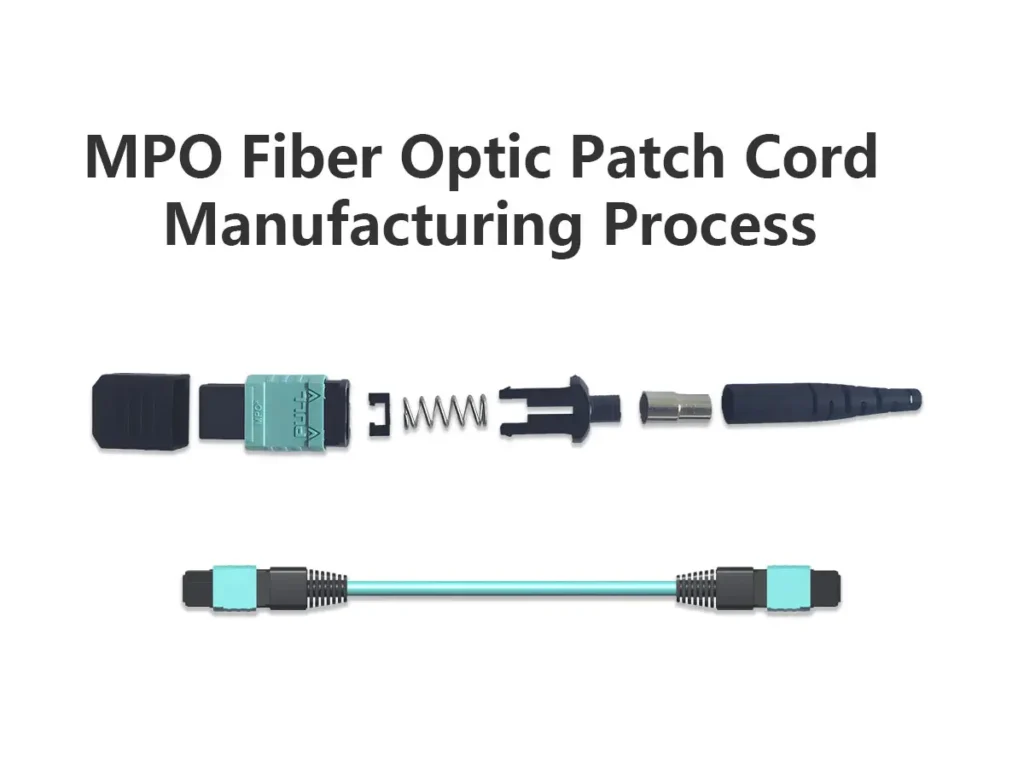
TABLE OF CONTENTS
Why MPO Patch Cord Manufacturing Requires Higher Precision
In a standard LC, SC, or FC patch cord, one ferrule usually aligns one fiber. In an MPO connector, one MT ferrule holds multiple fibers in a precise array. All fibers must be inserted, bonded, polished, and tested together. The connector also needs the correct male or female structure, pin configuration, Type A/B/C polarity, and accurate fiber mapping.
If you are looking for how standard LC, SC, or FC patch cords are produced, you can read our guide to the standard fiber optic patch cord manufacturing process. MPO manufacturing follows some similar principles, but the process is more sensitive because every step affects multiple fiber channels at the same time.
If fiber order is reversed, the finished cable may fail polarity verification. If epoxy volume is uneven, some fibers may have unstable bonding or different fiber height after polishing. If polishing pressure is not controlled, the MT ferrule geometry may fall outside the required range.
MPO Patch Cord Manufacturing Workflow
A typical MPO cable assembly manufacturing process includes twelve main steps:
- material and work order confirmation
- cable cutting
- component pre-assembly and cable stripping
- fiber arrangement
- fiber coating stripping and alcohol cleaning
- pin and MT ferrule installation
- epoxy dispensing and curing
- multi-step endface polishing
- 3D testing and inspection
- connector housing assembly
- insertion loss and return loss testing
- labeling and packaging.
Step-by-Step MPO Patch Cord Manufacturing Process
1. Material and Work Order Confirmation
Production starts with the work order. Before cutting cable or preparing connector parts, the factory checks fiber count, fiber type, cable length, connector gender, polarity, endface type, label requirement, packaging method, and test standard. This step is important because similar-looking MPO cables can have different fiber mapping inside.
2. Cable Cutting

The cable is cut from the original reel according to the required length. For MPO trunk cables, breakout cables, and harness cables, the cutting process also needs to allow enough length for stripping, assembly, and connector installation. Accurate cutting keeps the finished batch consistent.
3. Component Pre-Assembly and Cable Stripping

Before fiber preparation, the connector parts are placed onto the cable in the correct order, including the cable boot, crimp band, spring push, strain relief parts, and other MPO connector accessories. The sequence matters because some parts cannot be added after the ferrule is installed. The cable jacket is then stripped carefully to expose the internal fibers without damaging the coating or creating stress near the connector body.
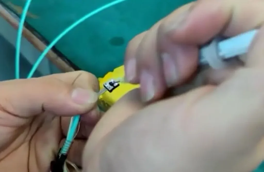
4. Fiber Arrangement

MPO cables are multi-fiber assemblies, so the fibers must be arranged in the correct order before entering the MT ferrule. The arrangement follows the work order and the required polarity, such as Type A, Type B, or Type C. During this step, technicians keep the fiber row clean and stable to prevent crossing, twisting, or incorrect mapping.
5. Fiber Coating Stripping and Alcohol Cleaning
After arrangement, the coating is stripped from the section that will enter the MT ferrule. The bare fibers are cleaned with alcohol to remove coating residue, dust, and contamination. Clean handling here reduces bonding problems, endface defects, optical loss, and rework.
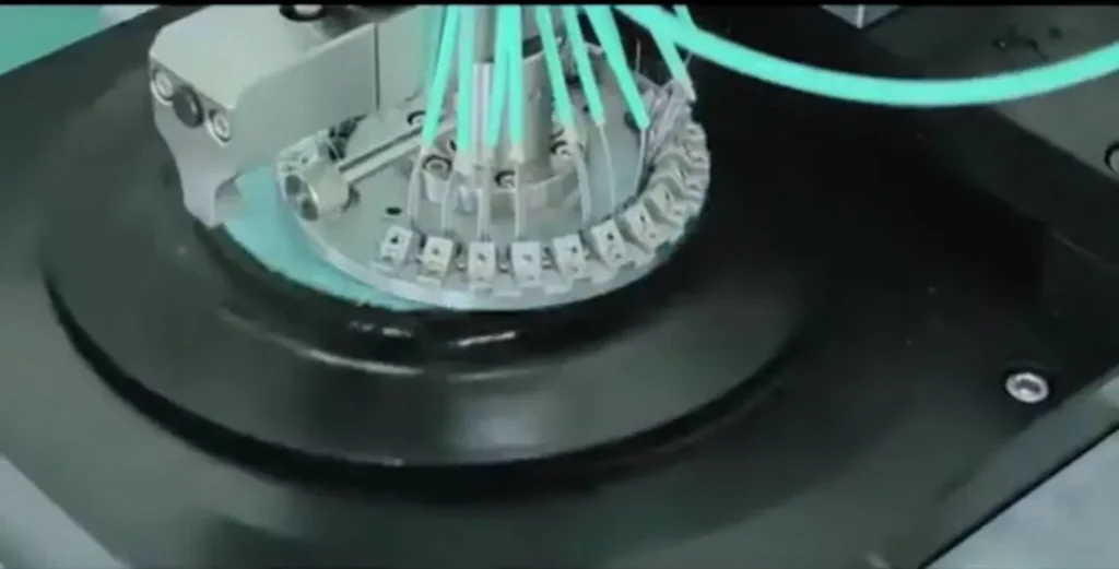
6. Pin and MT Ferrule Installation
The MT ferrule is the core part of an MPO connector. It contains multiple precision holes for the fiber array. For male MPO connectors, guide pins support alignment with a female connector. For female MPO connectors, the ferrule is unpinned. Incorrect gender or pin configuration can cause mismatch with panels, cassettes, transceivers, or mating cables.
7. Epoxy Dispensing, Glue Refill, and Curing
Epoxy is dispensed into the MT ferrule to bond the fibers. The amount must be controlled carefully: too little epoxy may cause weak bonding, while too much may overflow and affect polishing. After fiber insertion, glue refill may be performed to ensure internal support.
The ferrule is then cured under controlled conditions. Curing temperature and time must be stable so the epoxy hardens without bubbles, uneven bonding, or stress on the fibers. Because all fibers share one MT ferrule, one failed channel can require the whole ferrule to be reworked.
8. Multi-Step Ferrule Endface Polishing
MPO connector polishing is more demanding than single-fiber connector polishing because all fibers are polished together on one MT ferrule surface. The process normally includes epoxy removal, coarse polishing, fine polishing, and final polishing, using suitable films, fixtures, pressure, and time. Uneven polishing may cause scratches, pits, poor fiber height, high insertion loss, poor return loss, or failed endface inspection.
9. 3D Testing, Endface Inspection, and Polarity Verification


After polishing, the connector enters inspection before final housing assembly. A 3D interferometer can be used to check ferrule geometry, including fiber height, endface angle, apex offset, core protrusion or undercut, and overall endface consistency. These measurements help confirm whether the MT ferrule can provide stable physical contact during mating.
Technicians also inspect the endface under a microscope to check scratches, pits, residual epoxy, chips, dust, and contamination. Endface inspection is commonly evaluated with reference to IEC 61300-3-35, while ferrule geometry may be checked against applicable IEC 61755-series requirements and customer specifications. Polarity verification confirms fiber mapping and connector orientation before final assembly.
10. MPO Connector Housing Assembly

Only connectors that pass inspection proceed to housing assembly. At this stage, the outer housing, latch, push-pull boot, spring structure, and related mechanical parts are installed. Incorrect housing assembly may cause poor fit, weak latch performance, unstable mating, or wrong polarity orientation.
11. Insertion Loss and Return Loss Testing
The finished MPO patch cord is tested for insertion loss and return loss according to customer-defined limits and commonly referenced IEC 61300-series test methods. Multi-channel testing is required because every fiber channel must meet the specification. If one channel has high insertion loss or unstable return loss, the connector may need to be cleaned, rechecked, re-polished, or reworked.
12. Labeling and Packaging
After testing, the cable is labeled and packaged according to the work order. Labels may include polarity, length, fiber count, connector type, batch information, customer part number, or OEM branding. Protective packaging keeps the endface clean during storage and transport.
Quality Control Points in MPO Patch Cord Manufacturing
| Process | Main Risk | Factory Control |
|---|---|---|
| Work order confirmation | Wrong fiber count, polarity, gender, or label | Confirm specifications before production and keep batch records |
| Fiber arrangement | Wrong fiber mapping or polarity | Arrange fibers according to Type A/B/C and verify before final assembly |
| Epoxy and curing | Weak bonding, bubbles, uneven fiber height | Control epoxy volume, refill condition, curing time, and temperature |
| Polishing | Scratches, pits, poor geometry, high loss | Use controlled polishing films, fixture pressure, and inspection |
| 3D and endface inspection | Geometry failure or contamination | Check ferrule geometry, endface cleanliness, and visible defects |
| IL/RL testing | One or more failed channels | Test every channel and issue performance records when required |
| Labeling and packaging | Installation confusion or endface contamination | Apply correct labels, dust caps, and protective packaging |
Common MPO Manufacturing Defects and How Factories Prevent Them
High insertion loss is often related to poor polishing, contamination, fiber damage, incorrect mating, or unstable fiber height. Poor return loss can be caused by endface geometry problems, APC/UPC mismatch, poor contact, or scratches. Wrong polarity usually comes from incorrect fiber arrangement, wrong key orientation, or a mismatch between the work order and actual assembly. This is why MPO quality control should cover mechanical assembly, ferrule geometry, endface cleanliness, polarity, and optical performance together.
Industry Standards Commonly Referenced in MPO Testing
MPO patch cords can be tested according to customer requirements and commonly referenced industry standards.
For connector interface and mechanical compatibility, MPO connector design is commonly associated with IEC 61754-7. For endface visual inspection, factories often refer to IEC 61300-3-35. For ferrule geometry and optical interface requirements, the IEC 61755 series is commonly referenced. Insertion loss and return loss testing can be performed according to applicable IEC 61300-series methods, such as IEC 61300-3-4 for attenuation and IEC 61300-3-6 for return loss. Multi-fiber connector reliability may also be evaluated with reference to Telcordia GR-1435 and project-specific requirements. For structured cabling and polarity planning, the TIA-568 optical fiber cabling standard family is also relevant.
These references should not replace the customer’s own specification. The factory should confirm the required standard, test method, and acceptance limit before mass production.
What to Check When Choosing an MPO Patch Cord Manufacturer
When evaluating an MPO patch cord manufacturer, buyers should look beyond the product photo or basic specification sheet. A reliable factory should confirm polarity, gender, fiber count, endface type, cable length, and labeling before production. It should also have controlled MT ferrule assembly, multi-step polishing, 3D inspection capability, endface inspection, IL/RL testing, and batch quality records. For OEM buyers and project contractors, the key question is whether the supplier can keep repeat orders and bulk batches consistent.
FAQ
How is an MPO patch cord manufactured?
An MPO patch cord is manufactured through material confirmation, cable cutting, component pre-assembly, fiber arrangement, coating stripping, MT ferrule installation, epoxy dispensing and curing, ferrule polishing, 3D inspection, endface inspection, polarity verification, housing assembly, IL/RL testing, labeling, and packaging.
Why is MPO patch cord manufacturing more complex than standard patch cords?
MPO patch cords use an MT ferrule that holds multiple fibers in one connector. All fibers must be arranged, bonded, polished, and tested together. The factory must also control polarity, gender, pin configuration, and multi-channel optical performance.
What is the most critical step in MPO production?
Fiber arrangement, epoxy curing, polishing, 3D inspection, and IL/RL testing have the greatest impact on final performance.
Why does MPO polarity need to be checked before final assembly?
Polarity determines whether the transmit and receive fibers connect correctly in the network. If fiber mapping is wrong, the cable may not work even if insertion loss is acceptable.
What tests are required for MPO fiber optic patch cords?
Common tests include insertion loss, return loss, polarity verification, endface inspection, and 3D interferometer testing. Acceptance limits should follow customer requirements and applicable standards.
Why can one failed fiber channel cause the whole MPO connector to fail?
All fibers in an MPO connector share one MT ferrule. If one channel has high loss, poor geometry, contamination, or damage, the connector may need to be re-polished, cleaned, or reworked as a whole.
Can MPO patch cords be customized by fiber count, polarity, and cable length?
Yes. MPO patch cords can be customized by fiber count, fiber type, connector gender, polarity, endface type, cable length, label, and packaging. For data center, telecom, and high-density cabling projects, these specifications should be confirmed before sampling or mass production.
Conclusion
The MPO patch cord manufacturing process requires precise control from the first work order review to the final test report and packaging. A high-quality MPO cable assembly depends on correct fiber arrangement, stable MT ferrule bonding, controlled polishing, clean endface inspection, accurate polarity verification, and full-channel IL/RL testing.
For data centers, telecom networks, AI infrastructure, and high-density cabling systems, choosing the right manufacturer helps reduce polarity mistakes, insertion loss problems, contamination risk, and batch inconsistency. If you need custom MPO fiber optic patch cords for bulk projects, OEM supply, or project-specific cabling requirements, YingFeng can support different fiber counts, polarity types, connector genders, cable lengths, testing requirements, labeling, and packaging.
Source
- IEC 61754-7, Fibre optic interconnecting devices and passive components – Fibre optic connector interfaces – Part 7: MPO connector family.
- IEC 61300-3-35, Fibre optic interconnecting devices and passive components – Basic test and measurement procedures – Part 3-35: Visual inspection of fibre optic connectors and fibre-stub transceivers.
- IEC 61755 series, Fibre optic interconnecting devices and passive components – Connector optical interfaces.
- IEC 61300-3-4, Fibre optic interconnecting devices and passive components – Basic test and measurement procedures – Part 3-4: Attenuation.
- IEC 61300-3-6, Fibre optic interconnecting devices and passive components – Basic test and measurement procedures – Part 3-6: Return loss.
- Telcordia GR-1435, Generic Requirements for Multi-Fiber Optical Connectors.
- TIA-568.3, Optical Fiber Cabling and Components Standard.