
İÇİNDEKİLER
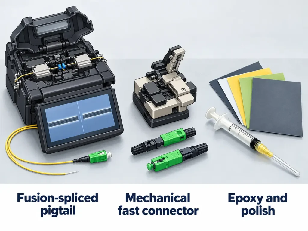
Fiber optik kablonun sonlandırılması, her bir optik fiberin bir konektörle tamamlanması ve böylece alıcı-verici, bağlantı paneli veya başka bir kablo gibi ekipmanlara takılabilmesini sağlamaktır. Sahada bunu yapmanın üç yolu vardır: fabrikada üretilmiş bir pigtail'i fiber üzerine füzyon ekleme, mekanik hızlı bir konektör takma veya konektörü epoksi ile yapıştırıp uç yüzeyini elle parlatma. Çoğu tek modlu saha sonlandırmasında ekli pigtail veya eklemeli konektör kullanılırken, çok modlu fiber genellikle doğrudan sonlandırılır.[1]
Aşağıdaki tabloda, üç yöntem kayıp, süre ve kullanılan araçlar açısından karşılaştırılmaktadır; bunu, her bir yöntem için gerekli adımlar ve kontrol noktaları ile sonlandırmanın başarılı olduğunu kanıtlayan testler izlemektedir. Sahada ekleme cihazı bulunmayan FTTH bağlantı kabloları için mekanik hızlı konektörler genellikle tercih edilir ve bir fiberin sonlandırılması bir dakikadan az sürer;[2] bizimkiler şu başlık altında listelenmiştir: fiber optik hızlı konektörler.
Fiber Optik Kabloyu Sonlandırmak Ne Anlama Gelir?
Fiber optikte, fiberler iki şekilde birleştirilir. Bir konektör geçici bir bağlantı sağlar: bir adaptör aracılığıyla başka bir konektörle birleşir ya da fiberi Ethernet anahtarı gibi ağ ekipmanlarına takar. Bir ekleme ise iki fiber arasında kalıcı bir bağlantı oluşturur.[1] Kurulumcular fiber optik kablo sonlandırmasından bahsettiklerinde, genellikle ilk seçeneği kastederler: cam elyafın ucuna bir konektör takmak; bu, doğrudan yapılabileceği gibi, halihazırda bir konektörü bulunan kısa bir elyafın üzerine ekleme yoluyla da gerçekleştirilebilir.
Her iki durumda da sonuç, aynı iki sayı üzerinden değerlendirilir. Ekleme kaybı, iki konektörün birleştiği yerdeki ışık kaybıdır; yansıma kaybı ise yansıma oranının tersi olup, kaynağa doğru ne kadar ışığın geri yansıdığını ölçer. Temiz ve iyi yapılmış bir sonlandırma, her ikisini de bağlantının sınırları içinde tutar; kirli veya kötü kesilmiş bir sonlandırma ise kablo kendisi mükemmel olsa bile arızaya neden olabilir. Her iki ölçüm de Ekleme kaybı ve geri dönüş kaybı ne anlama gelir?.
Fiber Bağlantısını Sonlandırmanın Üç Yolu ve Nasıl Seçim Yapılır
| Yöntem | Nasıl çalışır? | Tipik kayıp | Lif başına süre | Temel araçlar | En uygun seçenek |
|---|---|---|---|---|---|
| Füzyonla birleştirilmiş pigtail | Fabrikada uçlandırılmış bir pigtail, kablo fiberine füzyon ekleme yöntemiyle eklenir | Fabrika çıkışı konektöründe genellikle 0,3 dB'nin altında,[1] ayrıca kayıp hesaplamalarında her füzyon eklemesi başına 0,1–0,2 dB[3] | Bir füzyon eklemesi ve kablo kanalı işleri | Füzyon ekleme makinesi, hassas kesici | Tek modlu, gevşek tüplü ve dış tesis kablosu; tek bir noktada çok sayıda fiber |
| Mekanik hızlı bağlantı elemanı | Fabrikada cilalanmış bir fiber ucu, yerleşik bir mekanik ekleme noktasında saha fiberiyle birleşir | Hassas kesiciyle yaklaşık 0,5 dB, basit kesiciyle ise genellikle 0,75 dB civarında[1] | Bir dakikadan az[2] | Soyma bıçağı, kesme bıçağı, montaj aleti | FTTH bağlantı kabloları, her seferinde birkaç bağlantı, sahada ekleme cihazı yok |
| Epoksi ve cila | Fiber, konektör manşonuna yapıştırılır, kesilir ve cilalanır | Fabrika cilalı tek modlu ve çok modlu konektörlerde genellikle 0,3 dB’nin altındadır; deneyimli kurulumcular sahada çok modlu konektörlerde de benzer sonuçlar elde edebilirler[1] | Sertleştirme fırını kullanılarak toplu işleme yönteminde konektör başına birkaç dakika[4] | Yapıştırıcı, fırın, parlatma filmi, mikroskop | Sahada çok modlu; fabrikalarda çoğunlukla tek modlu |
| Takılabilir konektör | Fabrika çıkışlı kısa bir pigtail içeren bir konektör, fiberle füzyon ekleme yöntemiyle birleştirilir | Konektör kaybı artı ekleme noktasındaki kayıp[2] | En fazla bir füzyon eklemi[2] | Füzyon ekleme makinesi, hassas kesici | Ek tepsisi için yer bulunmayan tek modlu sistem |
Rakamlar, her bir hücrede belirtildiği üzere farklı koşullardan elde edilmiştir: fabrikada parlatılmış konektörler, kayıp bütçesi tahminleri, tekli sonlandırmalar ve toplu işler. Bunları, yan yana yapılan bir testin sonucu olarak değil, her bir yöntem için tipik aralık olarak değerlendirin.
Sonlandırma yöntemi nasıl seçilir:
- Tek modlu kablo ve füzyon ekleme cihazı mevcuttur: pigtail uçlarını ekleyin veya ekleme tipi konektörler kullanın. Gevşek tüplü kablolar genellikle pigtail uçlarının eklenmesiyle sonlandırılır.[4]
- FTTH kabloları, her ziyaret başına birkaç bağlantı, ekleme cihazı yok: mekanik hızlı bağlantı elemanları.
- Çok modlu, iç mekan, çok sayıda konektör: epoksi ve cila. Deneyimli montajcılar bu yöntemle fabrika çıkışlı bağlantılarla karşılaştırılabilir sonuçlar elde edebilirler.[1]
- Kurulumdan önce bilinen kablo uzunlukları: kablo uçlarını atlayın ve önceden uçlandırılmış kablo sipariş edin.
FOA’nın 568-C baskısına ilişkin özetine göre, fiber optik sonlandırma yöntemi ne olursa olsun, TIA-568 standardı, birleştirilmiş her konektör çifti başına en fazla 0,75 dB’lik bir kayba izin vermektedir.[5] Bu rakam, kayıp bütçesi için bir üst sınırdır, bir kalite hedefi değildir; proje tarafları daha düşük değerler üzerinde anlaşabilirler.[5] Check which edition of the standard and which acceptance values the project specification names; a termination near 0.75 dB leaves little margin on a long link.

Before You Start: Tools, Clean Work and Safety
Every termination process starts with the same basic fiber optic termination tools, and each method adds its own:
| Yöntem | Tools in addition to the basic kit |
|---|---|
| All methods (basic kit) | Cable jacket stripper, fiber stripper, isopropyl alcohol and lint-free wipes, cleaver, fiber scrap container, visual fault locator |
| Füzyonla birleştirilmiş pigtail | Fusion splicer, heat-shrink splice protectors, splice tray, factory pigtails |
| Mekanik hızlı bağlantı elemanı | Fast connectors for the cable type, the connector maker’s assembly tool or cleave-length guide |
| Epoksi ve cila | Connectors, adhesive and syringe, crimp tool, curing oven (for heat-cured epoxy), polishing puck, pad and film, inspection microscope |
The cleaver deserves the most attention. In fusion and mechanical splicing alike, the secret to a good joint is a good cleave on both fibers.[1] Keep its blade clean and replace or rotate it as the maker recommends. Clean the bare fiber after stripping to remove dirt and scraps of the stripped buffer before it goes into a connector or splicer.[4]
Work safely with bare fiber
- Never look into a fiber end or bring it near your eye; a broken fiber can emit light at an angle.[6]
- Put every fiber scrap into a container, then seal it and dispose of it properly.[6]
- Isopropyl alcohol is flammable; handle it carefully and keep it away from heat sources.[6]
- Before inspecting a connector with a microscope, check with a power meter that the fiber is dark: a microscope can focus the light from a live fiber into your eye.[6]
How to clean connector end faces before mating is covered in our fiber optic cleaning guide.
Method 1: Fusion Splice a Factory Pigtail
Splicing a pigtail gives every fiber a factory-polished connector and a low loss joint, which is why it is the usual choice for single-mode cable. The steps, in brief:
- Slide a heat shrink splice protector onto the fiber before anything else.
- Strip the cable and the fiber coating, then clean the bare fiber.
- Cleave the cable fiber and the pigtail fiber.
- Fusion splice them with the splicer’s electric arc; most fusion splicers then display an estimated loss for the splice.
- Shrink the protector over the splice and coil the fibers into the splice tray.
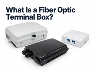
For loss budgets, figure 0.1–0.2 dB for each fusion splice.[3] The tray and its pigtails sit in a closure, a terminal box or an optical distribution frame; the box types are compared in what a fiber optic terminal box is, and pigtails in what a fiber pigtail is. Splicer setup, arc settings and fixing a bad splice are covered step by step in fiber optic splicing for beginners.

Method 2: Install a Mechanical Fast Connector
A mechanical fast connector, also called a field-installable or prepolished/splice connector, moves the hard part to the factory. A short stub fiber is glued into the ferrule and machine-polished, and the back of the connector holds a mechanical splice with index matching gel and a crimp that holds the field fiber.[2] One major manufacturer sums up the installation as “strip, clean, cleave, cam, and crimp”.[7]
The steps below follow a typical SC or LC fast connector on an FTTH drop or round cable. Check the connector installation instructions for strip and cleave lengths.
- Slide the boot and any cable clamp parts onto the cable.
- Strip the outer jacket to the length in the instructions (50–60 mm for YingFeng fast connectors), then strip the coating from the fiber.
- Clean the bare fiber with alcohol and a lint-free wipe.
- Cleave the fiber to the length the cleave guide gives. A precision cleaver gives more consistent loss than a simple one.[1]
- Push the fiber straight into the connector until it meets the stub. A slight bow in the fiber behind the connector shows that the two ends are touching.
- Hold the fiber in place and close the lock, then clamp the cable jacket.
- Fit the outer housing and the dust cap.
Checkpoint: connect a visual fault locator to the far end or the patch cord and watch the connector body. A visual fault locator can be used to verify and optimize mechanical splices and prepolished/splice connectors:[3] light lost at the internal splice shows through the connector, and keeping that light to a minimum gives the lowest-loss splice.[2] A bright glow can mean the fiber is not fully seated, a poor cleave or a dirty fiber end. If the connector’s instructions allow it to be reopened, re-seat the fiber and check again; otherwise, or if the glow stays, cut off the connector and re-terminate with a fresh cleave.
The two internal designs, with and without a pre-embedded stub, are compared in embedded vs non-embedded fast connectors.
Method 3: Epoxy and Polish a Connector
Most connectors, including virtually all factory-made terminations, are epoxy and polish types.[1] Factories use heat-cured epoxy and polishing machines; heat-cured epoxy is used less in the field because it needs an oven.[4] Adhesives for fiber connectors come in three general categories: epoxy, hot melt and anaerobic.[8] Each needs its own technique, and some epoxies cure overnight at room temperature instead of in an oven.[4] The steps below are the FOA’s general method for an epoxy connector; for curing and polishing, the connector and adhesive maker’s instructions take precedence.
- Slide the strain-relief boot over the cable, followed by the crimp bushing.[4]
- Strip the jacket and coating, then clean the fiber to remove dirt and buffer scraps.[4]
- Fill the connector with adhesive, insert the fiber, crimp the connector to the cable and cure the adhesive.
- Cleave the excess fiber sticking out of the ferrule.[4]
- Hand polish in three steps: an air polish with coarse film (about 12 micron grit), then a fine film (usually 3 micron), then a final film of about 0.3 to 1 micron. Always finish on a soft rubber pad.[4]
- Clean the connector again and inspect it in a microscope.[4]

Single-mode terminations need extreme care in assembly, especially in polishing, so they are usually done in a clean manufacturing facility with heat-cured epoxy and machine polishing.[1] In practice, field polishing is mostly a multimode job; single-mode links get factory-polished pigtails or patch cords. The difference between angled and flat end faces is explained in APC vs UPC.
Splice-On Connectors
Connectors with mechanical splices are usually called prepolished/splice connectors, and the ones joined by fusion are called splice-on connectors (SOCs).[2] A splice-on connector has a short factory pigtail behind the ferrule, which is fusion spliced to the field fiber, and the termination takes no longer than a fusion splice.[2] When testing, remember that the connection loss of this type includes the connector loss plus the loss of the splice that attaches it.[2] It suits single-mode jobs where a splicer is on site but there is no room for a splice tray.
When to Skip Field Termination
If cable lengths are known before installation, the fiber can be terminated and tested in a factory and arrive ready to plug in. Installers then pull cable and connect it, with no stripping, cleaving or polishing on site. The trade-off is planning: each length has to be measured in advance. With field termination, an installer cuts every cable to length on site; with pre-terminated cable, a run that turns out too short has to be reordered, and extra length has to be coiled and stored. Pre-terminated drops, multi-fiber trunks and plug-and-play FTTH systems are compared with field termination in pre-terminated fiber systems for FTTH.
Test and Troubleshoot Every Termination
Test each termination before the cable is closed up:
- Make sure the fiber is dark, then inspect the end face with a microscope, and clean it if needed. Visual inspection does not replace measuring attenuation and return loss.[9]
- Check continuity with a visual fault locator. These tracers inject visible light, which shows breaks and bad joints through buffered fiber and even single-fiber cable if the jacket is not opaque.[10]
- Measure end-to-end loss with an optical loss test set. Tier 1 testing covers insertion loss, length and polarity.[11] Compare the measured loss with the loss budget calculated for that link before testing: the fiber loss plus every connector pair and splice in it.[3] Under TIA-568 as summarized by the FOA, each mated connector pair may lose at most 0.75 dB and each fusion or mechanical splice at most 0.3 dB;[5] use those limits to build the budget, not to judge the link total.
- Add an OTDR trace where the project calls for it. An end-to-end loss test does not show the loss of each joint. An OTDR measures the loss and the reflectance of each connector and splice,[3] and Tier 2 OTDR testing complements the Tier 1 loss test rather than replacing it.[11] If the specification sets return loss values, measure them as it requires.
When a termination fails, the symptom usually points to the cause:
| Semptom | Likely cause | What to do |
|---|---|---|
| High loss on a new termination | Poor cleave or dirty fiber | Clean, re-cleave and redo the termination |
| Very poor return loss, or high loss at one connection | APC connector mated with a UPC connector | Use matching end faces at every adapter: APC to APC, UPC to UPC |
| Light glowing at a fast connector’s splice zone | Fiber not fully seated, poor cleave or dirty fiber end | Re-seat the fiber if the design allows; otherwise re-terminate with a fresh cleave |
| Loss changes when the cable is moved | Fiber bent too tightly behind the connector, or boot not fitted | Re-route the cable and refit the boot |
| High splice loss on the splicer | Dirty or chipped fiber ends | Clean, re-cleave and re-splice |
Fiber Termination Products from YingFeng
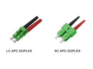
Fiber Optic Fast Connectors: SC/APC, SC/UPC and LC/APC pre-polished fast connectors for FTTH drop and round cables. View fast connectors
For field termination without a splicer, YingFeng makes SC/APC, SC/UPC and LC/APC hızlı konektörler of the pre-polished, embedded type, for FTTH drop cables and round cables, and every fast connector is optically tested before shipment. For splicing, fiber pigtails are available alongside our fiber optik bağlantı kabloları. For factory termination, we supply SC and LC connector kits and individual parts, and assembled connectors can be produced to your requirements on request. Samples are available. To get a quote, bize gönderin the cable type, connector and end face, and the quantity.
Sıkça Sorulan Sorular
Fiber optik kabloyu sonlandırmak için hangi aletlere ihtiyacınız var?
It depends on the method. Every method needs strippers, a cleaver, alcohol and wipes, and a visual fault locator. Fusion splicing adds a splicer and splice protectors; fast connectors need only the connector maker’s assembly tool; epoxy and polish adds adhesive, a curing oven for heat-cured epoxy, polishing film and a microscope. Acceptance testing needs an optical loss test set, plus a power meter to confirm a fiber is dark before inspection, and an OTDR where the project specifies one.
Fiber optik kabloyu kesmek zor mu?
Mechanical fast connectors are the easiest to learn, but results still depend on a good cleave and clean fiber. Polishing single-mode connectors is difficult and is usually left to factories.[1] For emergency fixes to a damaged cable, see fiber optik kablo nasıl onarılır.
Bir saha sonlandırmasında ne kadar kayıp kabul edilebilir?
TIA-568, as summarized by the FOA for the 568-C edition, allows up to 0.75 dB per mated connector pair, and a project can agree on lower values.[5] A fast connector installed with a precision cleaver typically comes in around 0.5 dB.[1] Check the measured total against the loss budget of the whole link.
Bir fiber kablosunu kesmek ne kadar sürer?
Tek modlu fiberin uçlarını sahada epoksi ile kapatıp cilalayabilir misiniz?
Bu yapılabilir, ancak tek modlu cilalama işlemi son derece özen gerektirdiğinden, sahada yapılan tek modlu sonlandırmaların çoğunda bunun yerine ekli bir pigtail veya ekleme tipi konektör kullanılır.[1]
Dış kaynaklar
- Fiber Optik Derneği: Fiber Optik için FOA Kılavuzu – Uçlandırma
- Fiber Optik Derneği: The FOA Reference for Fiber Optics – Splice-On Connectors
- Fiber Optik Derneği: The FOA Reference for Fiber Optics – Outside Plant Fiber Optic Testing
- Fiber Optik Derneği: The FOA Reference for Fiber Optics – Hints for Terminating Fiber Optic Connectors
- Fiber Optik Derneği: EIA/TIA 568 for Fiber Optics (summary of TIA-568-C)
- Fiber Optik Derneği: The FOA Reference for Fiber Optics – Safety
- Corning: UniCam Frequently Asked Questions (product documentation)
- Fiber Optik Derneği: The FOA Reference for Fiber Optics – Adhesive/Polish Connectors
- IEC 61300-3-35:2022, Fiber optik bağlantı cihazları ve pasif bileşenler – Bölüm 3-35: Fiber optik konektörlerin ve fiber uçlu alıcı-vericilerin görsel muayenesi: IEC İnternet Mağazası
- Fiber Optik Derneği: The FOA Reference for Fiber Optics – Visual Fault Location
- Fluke Networks: 1. ve 2. seviye fiber testleri için ipuçları (Cabling Chronicles blogu)