
TABLE OF CONTENTS
A fiber optic splitter is simple in purpose but consequential in a network design: it shares optical power from one feeder path across multiple downstream paths. For FTTx planners, contractors, installers and buyers, the real question is not only what a splitter is. It is whether the selected split ratio, interface, package and optical performance leave enough margin for every planned path. This guide explains the working principle, compares PLC and FBT technologies, and provides a practical selection sequence for PON and related optical distribution applications.
What Is a Fiber Optic Splitter in a PON?
A fiber optic splitter is a passive optical branching component. It distributes optical power from one input fiber to multiple output fibers without an electrical power supply. In a passive optical network, it sits in the optical distribution network between the central-office equipment and the downstream endpoints.
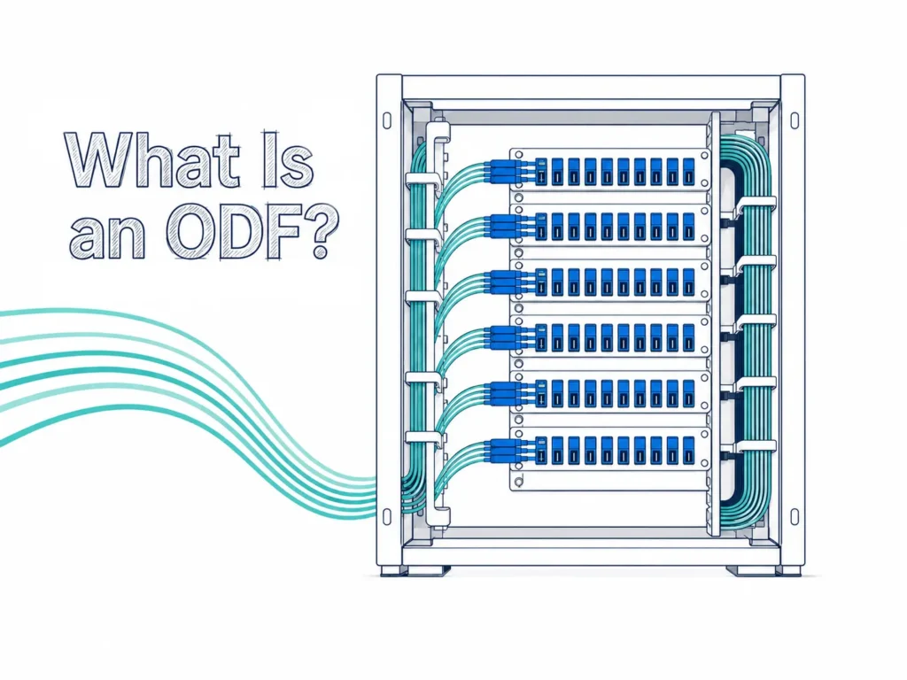
The splitter is one component in the optical distribution network (ODN). The ODN links the optical line terminal (OLT) to the downstream optical network units (ONUs) or ONTs. The splitter divides light; it does not act as an Ethernet switch, create independent point-to-point links, amplify the signal or decide which subscriber receives traffic. Those functions belong to the active PON equipment and its protocol.
How Does a Fiber Optic Splitter Work?
An equal 1xN splitter divides the available input optical power across N output ports. A 1×8 device aims to deliver approximately one eighth of the input power to each output, while a 1×16 device aims to deliver approximately one sixteenth. The optical signal is not copied at full power. Each split reduces the power available at an individual output, which is why split ratio and optical budget must be evaluated together.
For equal splitting, the ideal division loss is 10 x log10(N) dB. That is a useful planning starting point, not the complete component loss. A real splitter also has excess loss, and the installed route adds fiber attenuation, mated-connector loss, splice loss and any other passive devices. Use the maximum insertion loss of the exact proposed model in a project budget.
| Equal split | Ideal division loss only | Planning interpretation |
|---|---|---|
|
1×2 |
3.01 dB |
Start with the model maximum IL, not only this value. |
|
1×4 |
6.02 dB |
Add excess loss and all route losses. |
|
1×8 |
9.03 dB |
Check every planned path, not only an average path. |
|
1×16 |
12.04 dB |
Verify the exact package, fiber and connector configuration. |
|
1×32 |
15.05 dB |
Check the shortest and longest paths against equipment limits. |
Table 1. Ideal equal-split loss is a physics calculation; it excludes model-specific excess loss and installed-path loss.
PLC vs. FBT Splitters: Which Technology Fits the Design?
PLC and FBT splitters are not interchangeable labels. PLC splitters use a planar waveguide circuit and are widely used for equal, multi-output distribution across the single-mode access-network wavelength range. FBT splitters are fused-fiber couplers and can be appropriate for selected low-count, wavelength-specific or asymmetric coupling requirements. The correct choice follows the topology and specification, not a generic claim that one technology is always better.
| Decision factor | PLC splitter | FBT splitter |
|---|---|---|
|
Optical structure |
Planar waveguide circuit with fiber interfaces |
Fused and tapered optical fibers |
|
Typical design fit |
Equal multi-output distribution in PON/FTTx |
Selected low-count or asymmetric coupling needs |
|
Wavelength approach |
Broadband PLC configurations are common |
Confirm the selected wavelength window for the exact device |
|
High port counts |
Commonly selected for compact equal-ratio configurations |
Evaluate carefully as cascaded stages and variation can matter |
|
Buyer action |
Confirm ratio, max. IL, uniformity, PDL, interface and package |
Confirm ratio, operating window, loss, temperature behavior and package |
Table 2. A design comparison, not a contractual specification. Evaluate the data sheet and project requirements for the chosen model.
YingFeng’s primary focus is PLC splitter configurations. Equal-ratio PLC splitters are the normal choice for many FTTH, PON and CATV distribution designs. An unequal split can be useful when a topology and power budget explicitly require a different allocation of optical power, but it should be reviewed as a system decision rather than substituted for a standard 1xN splitter without calculation.
Inside a PLC Splitter: Why Assembly Control Matters
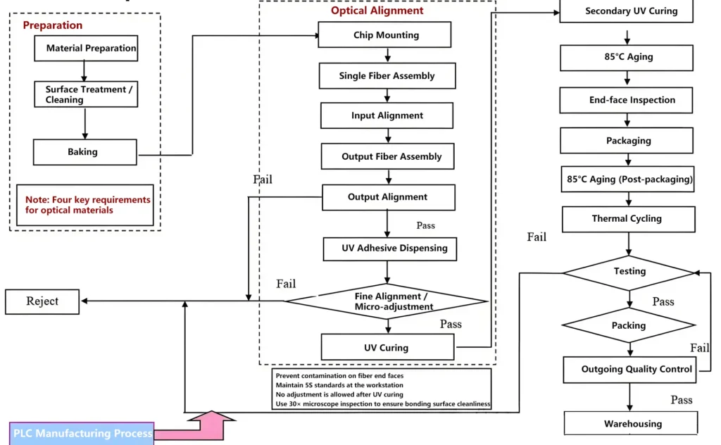
A typical PLC splitter assembly brings together a PLC chip, a fiber array and input/output fiber interfaces. The optical result depends not only on the chip design but also on how these parts are positioned, bonded, protected and verified. Alignment affects coupling efficiency and channel balance. Clean optical-contact surfaces and controlled adhesive curing help prevent avoidable optical and mechanical variation. Package protection then matters during handling, installation and environmental exposure.
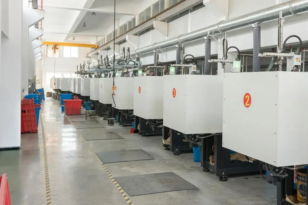
The manufacturing flow available for this guide is best understood as an illustrative PLC splitter assembly and quality-control flow: material preparation and cleaning; chip and fiber assembly; input/output optical alignment; adhesive dispensing, micro-adjustment and UV curing; inspection, aging, packaging and final testing. Exact sequences, aging conditions and acceptance limits vary by product design and factory quality plan. The useful buyer question is therefore not whether a factory shows a long process chart, but whether it can tie the proposed model to optical test records and applicable reliability evidence.
How to Choose a Fiber Optic Splitter: A Five-Step Workflow
- Define the network role. Identify the PON technology, OLT/ONT or ONU optical class, proposed topology, endpoint capacity and the intended splitter location. A desired output count alone is not a design input.
- Build the shortest and longest optical paths. Include each splitter stage, fiber section, splice, mated connector and coexistence component at the relevant wavelengths. A path can fail because it has too much loss; a short path can also require checking against the equipment’s permitted receive range.
- Choose the split pattern and technology. Use an equal PLC ratio where equal distribution and broadband access-network operation are required. Escalate unequal ratios, cascaded architecture or unusual wavelength needs for engineering review.
- Match the physical configuration. Confirm input/output connector type and polish, fiber type, pigtail length, cable diameter, package, mounting interface, host enclosure, access frequency and route management.
- Freeze the model and evidence before purchase. The order should reference a current data sheet, drawing, optical limits, test method/report format and acceptance criteria. Do not approve a part merely as ‘GPON grade’ or ‘PLC splitter’.
How to Read a PLC Splitter Data Sheet
Insertion loss is central, but it is not the only field that matters. Uniformity indicates how closely output-port losses track one another. PDL shows how loss changes with polarization. Return loss or directivity addresses unwanted optical effects in the opposite direction. Wavelength range, fiber type, connector polish, package, cable dimensions and environmental rating determine whether a nominally similar device actually fits the route and enclosure.
| Example configuration | Key data from supplied product information | Use in a project |
|---|---|---|
|
1×8 module PLC, SC/APC, G657A2 |
1260-1650 nm; IL = 55 dB; uniformity <= 0.8 dB; PDL = 55 dB |
Example configuration only. Verify the ordered model, pigtail length, cable, package and test conditions. |
|
1×16 LGX PLC, SC/UPC, G657A1 |
1260-1650 nm; IL = 50 dB; uniformity <= 1.0 dB; PDL = 55 dB |
Example configuration only. Confirm the installed LGX cassette and interface plan. |
Table 3. Configuration examples based on product data supplied by YingFeng. They are not universal PLC splitter specifications and should not replace a model-specific data sheet.
Whether a splitter is delivered with connectors is configuration-dependent. Read the supplied data as the performance statement for that configuration: if the splitter is supplied with connectors, the stated product figure applies to that configured product; if it is supplied without connectors, use the stated figure for that unterminated configuration and account for the installed interfaces in the route budget.
The supplied product information lists GR-1209 / GR-1221 as compliance references. For a project that requires formal qualification evidence, request the relevant model, report scope, test conditions and document version. The standard name by itself is not a substitute for a project acceptance record.

Choosing the Package for the Installation Location
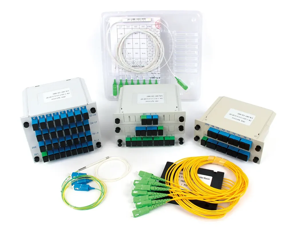
Choose the optical design first, then choose the package that fits the installation. Bare-fiber and mini-module formats can suit protected trays where space is tight. ABS box, LGX cassette and rack-mount formats can make connector access, organization or density easier when the host enclosure supports them. The package decision should cover mechanical protection, mounting space, cable routing, bend management, maintenance access and the environmental responsibility of the host enclosure.
When the splitter will be housed in a cabinet or termination point, also check the relevant fiber distribution box or enclosure drawing. Do not infer an IP rating, a minimum bend radius or an outdoor temperature range from the word ‘splitter’ alone; those claims belong to the exact enclosure, cable and product configuration.
Troubleshooting High Loss or Unstable PON Links
A splitter should not be blamed before the complete optical path is checked. Start with measured optical levels and available records. Then compare the actual route against the approved loss budget and inspect the interfaces and physical installation. This order prevents repeated component replacement when the cause is a dirty end face, an incompatible mating interface, an unrecorded splice, excessive bending or a changed route.
| Observed symptom | First checks | Evidence to retain |
|---|---|---|
|
ONU/ONT does not register after a split change |
Confirm actual receive level, split stage, OLT/ONT class and complete path loss. |
Power measurement, current port map and path-loss calculation. |
|
Unexpectedly high loss on one output |
Inspect end faces and mating interfaces; compare output readings and check splices/bends. |
Port-by-port test results and OTDR/power-meter record where applicable. |
|
Uneven output performance |
Compare against the model’s uniformity limit and rule out connector, splice or measurement setup variation. |
Test wavelength, fixture condition and output-port results. |
|
Gradual outdoor degradation |
Check enclosure sealing, cable protection, strain relief and route condition. |
Site inspection record and the enclosure/product specification. |
Table 4. A troubleshooting sequence, not a replacement for site safety procedures or the project’s test plan.
Frequently Asked Questions
How much loss does a 1x32 splitter add?
The ideal equal division loss of 1×32 is 15.05 dB. The installed result is higher because a real component has excess loss and the path also includes fiber, connectors, splices and other devices. Use the maximum insertion loss in the exact model data sheet, then calculate every installed path.
Does a higher split ratio reduce subscriber speed?
A higher split ratio primarily reduces optical power per output and increases the number of endpoints sharing a PON port. The delivered service result depends on the PON equipment, permitted optical range, service profiles and traffic capacity. It is not correct to treat split ratio as a simple speed setting.
Can APC and UPC connectors be mated directly?
Each direct connector-to-connector mating pair should use the specified compatible interface and polish. Hybrid patch assemblies can be designed with a different connector type at each end when each end mates to the correct port. Do not use a hybrid lead as permission to mate incompatible end faces directly.
Can a passive splitter replace an Ethernet switch or ordinary media-converter links?
No. A passive splitter only distributes optical power. A PON requires compatible OLT and ONT/ONU equipment and its control protocol. For independent point-to-point Ethernet links, use an architecture designed for that purpose rather than adding a passive splitter to a normal media-converter link.
What should a buyer request before approving a PLC splitter?
Request the exact ratio, technology, operating wavelength, maximum IL, uniformity, PDL, return loss/directivity, fiber and connector configuration, pigtail length, package drawing, operating environment, test method/report format and any project-specific qualification evidence.
From a Design Requirement to the Right Configuration
A successful splitter choice begins with the route and equipment, not with the lowest unit price or the highest available output count. Once the optical budget, split pattern, interfaces, host enclosure and acceptance requirements are defined, the required product configuration becomes much clearer. If you already have those inputs, review the available fiber optic splitter configurations and request a model-specific data sheet for project review.
Sources
- YingFeng product-data samples supplied for this article.Configuration examples include a 1×8 module PLC splitter with SC/APC and G657A2 fiber, and a 1×16 LGX PLC splitter with SC/UPC and G657A1 fiber. Supplied August 2026.
- YingFeng PLC splitter assembly and quality-control flow.Internal process diagram supplied by YingFeng. Used as an illustrative manufacturing flow; product-specific conditions are not claimed.
- ITU-T G.671, Transmission characteristics of optical components and subsystems.Official publication
- IEC 61753-1:2018, Fibre optic interconnecting devices and passive components – Performance standard – Part 1: General and guidance.Official standard listing
- Corning Optical Communications generic specification for passive optical components.Product-family specification
- AFL Global, Planar Lightwave Circuit PLC Splitters.Product reference