
If you’re just stepping into the world of fiber optics, all the technical terms and abbreviations can feel overwhelming. That’s why I created this fiber glossary series — to help you understand what these terms really mean, in the simplest way possible.
I’ll explain everything from an industry insider’s point of view, using real photos whenever I can (not just fancy renders). I also avoid overly complex explanations, keeping the language clear and direct, so you can be confident you’ll understand the real meaning of these terms after reading.
Today, we’re going to talk about: Polarization-Maintaining (PM) Fiber
TABLE OF CONTENTS
Quick Answer: What Is PM Fiber?
Polarization-maintaining fiber, usually called PM fiber, is a special optical fiber designed to keep a linearly polarized light signal aligned with one of two built-in axes as it travels.
Ordinary single-mode fiber carries one spatial mode, but this does not mean that it keeps one stable polarization state. Small bends, pressure, temperature changes, and manufacturing variations can change the polarization. PM fiber reduces this unwanted mixing by creating a strong and controlled difference between two polarization axes.
The most important point is simple: PM fiber maintains a correctly launched polarization state. It does not create polarized light from unpolarized light.
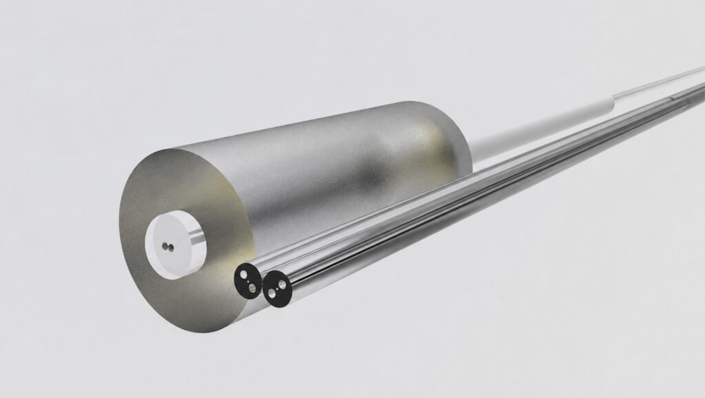
Image source: Vlink
What Does “Polarization” Mean?
Light is an electromagnetic wave. Its electric field moves in a direction while the light travels forward. Polarization describes how that direction behaves.
For linearly polarized light, the electric field mainly moves along one fixed direction. Some optical systems need this direction to stay stable. Examples include fiber gyroscopes, interferometers, coherent communication systems, lasers, and sensing equipment.
If the polarization drifts, the system may lose measurement accuracy, power, or stability. This is why PM fiber exists.
Why Does Ordinary Single-Mode Fiber Not Keep Polarization Stable?
The name “single-mode fiber” can be confusing. It means the fiber carries one main spatial mode. It does not mean that only one polarization can travel through it.
Two perpendicular polarization components can still travel in standard single-mode fiber. In an ideal, perfectly symmetrical fiber, they would behave almost the same. Real fiber is never perfectly free from stress. Bending, squeezing, temperature changes, cabling, and connector handling can all disturb it.
These disturbances change the relationship between the two polarization components. The output polarization can therefore change even when the input stays the same.
How Does PM Fiber Work?
PM fiber deliberately creates a property called birefringence. In simple terms, the fiber gives two perpendicular polarization directions slightly different optical conditions.
These two directions are called the fast axis and the slow axis.
- Light aligned with the fast axis has a slightly lower effective refractive index.
- Light aligned with the slow axis has a slightly higher effective refractive index.
Because the two axes behave differently, light launched along one axis is less likely to couple into the other axis. The polarization is therefore more stable.
Stress-applying parts create the two axes
The best-known design is PANDA fiber. It places two stress-applying rods beside the core. As the glass cools during manufacturing, these rods create controlled stress around the core. That stress produces the fast and slow axes.
Other designs, such as bow-tie and elliptical-clad fiber, create birefringence in different ways. The basic purpose is the same: keep the two polarization axes clearly separated.
Input alignment is critical
PM fiber only works as intended when polarized light is aligned with one principal axis at the input.
If the light enters at an angle between the axes, part of the power travels on each axis. The two parts collect phase at different rates. The output polarization may then become elliptical or change with wavelength, temperature, and length.
This is why PM connectors, splices, and assemblies require rotational alignment. The connector key is normally referenced to a chosen axis, but the exact convention must be confirmed on the drawing or datasheet. A low-loss connection can still have poor polarization performance if the axes are misaligned.

Three Simple Terms Worth Knowing
Birefringence
Birefringence is the difference between the effective refractive indices of the two axes:
B = |n_fast − n_slow|
A larger difference generally makes unwanted coupling between the axes less likely.
Beat length
Beat length is the distance over which the two polarization components build up a full 360-degree phase difference:
L_b = λ / B
Here, λ is wavelength and B is birefringence. A shorter beat length means stronger birefringence. Beat length should always be compared at the stated wavelength.
Polarization extinction ratio
Polarization extinction ratio, or PER, compares the power in the wanted axis with the power in the unwanted axis:
PER (dB) = 10 log10(P_wanted / P_unwanted)
A higher PER is better. For example, 20 dB means the wanted-axis power is 100 times the unwanted-axis power. The measured result depends on the source, launch alignment, fiber length, connectors, splices, bending, and test method.
Manufacturers may also specify polarization crosstalk as a negative value. In that case, a more negative result is better. Always check which measurement the datasheet uses.
Common Types of PM Fiber
| Type | How it creates birefringence | Typical reason to use it |
|---|---|---|
|
PANDA |
Two stress rods sit beside the core |
Widely available and commonly used for communication, sensing, and laser assemblies |
|
Bow-tie |
Bow-tie-shaped stress regions surround the core |
Strong stress-induced birefringence for specialty applications |
|
Elliptical-core or elliptical-clad |
An asymmetric core or cladding creates two axes |
Used where a different geometry or specialty design is needed |
PANDA is the name most buyers will see, but the fiber type alone does not prove that it fits an application. Wavelength, coating, attenuation, dimensions, PER or crosstalk, and environmental needs still matter.
PM Fiber vs. Other Fiber Types
| Fiber type | Main purpose | Does it preserve polarization? | Important note |
|---|---|---|---|
|
Standard single-mode fiber |
Carry one spatial mode over long distances |
Not reliably |
Polarization can drift with stress and temperature |
|
Polarization-maintaining fiber |
Keep light aligned to a chosen axis |
Yes, when launched and handled correctly |
It does not polarize unpolarized light |
|
Single-polarization fiber |
Guide one polarization while strongly suppressing the other |
Yes, within its designed wavelength range |
It works differently from ordinary PM fiber |
Do not choose PM fiber only because a system uses single-mode light. Many normal telecom links do not need polarization maintenance.

How to Read a PM Fiber Datasheet
1. Operating wavelength and cutoff wavelength
PM fibers are designed for particular wavelength regions, such as 850, 1060, 1310, or 1550 nm. Confirm that the operating wavelength is inside the specified range. Also check the cutoff wavelength so the fiber operates in the intended single-mode region.
2. Beat length
Shorter beat length usually indicates stronger birefringence. Compare values only when wavelength and test conditions are similar.
3. PER or polarization crosstalk
This tells you how well the assembly keeps power on the chosen axis. A bare-fiber value is not automatically the same as the result of a finished patch cord. Connector alignment, splicing, bending, and handling can reduce performance.
4. Attenuation
Attenuation shows optical loss per unit length, usually in dB/km. For short PM assemblies, connector and splice losses may matter more than the fiber’s kilometer-level attenuation.
5. Mode field diameter and numerical aperture
These values affect coupling and splice compatibility. A mismatch between two fibers can create extra loss, even if both products are described as PM fiber.
6. Cladding, coating, and buffer
Check the glass diameter, coating diameter, coating material, and temperature range. Standard acrylate, high-temperature coatings, and metal coatings serve different environments.
7. Bend requirements
Bending can add loss and disturb polarization. Follow the supplier’s minimum bend radius and test conditions. Our fiber bend radius guide explains the basic difference between macrobending and microbending.

A Real Datasheet Example
Corning’s PANDA PM 1550 datasheet, issued in January 2019, lists these values for that specific product:
| Parameter | Published value and condition |
|---|---|
|
Operating wavelength |
1550 nm |
|
Maximum attenuation |
0.5 dB/km at 1550 nm |
|
Mode field diameter |
10.5 ± 0.5 µm at 1550 nm |
|
Beat length |
3.0 to 5.0 mm at 1550 nm |
|
Maximum crosstalk |
−30 dB at 100 m |
|
Typical crosstalk |
−40 dB at 4 m |
These are not universal PM fiber values. They are a useful example of how specifications are tied to wavelength and test length. A buyer should compare the actual datasheet for the exact fiber or cable assembly being considered.
Where Is PM Fiber Used?
Common applications include:
- Fiber-optic gyroscopes and navigation systems
- Interferometric and current sensors
- Coherent optical communication
- Fiber lasers and laser delivery systems
- Polarization-sensitive test equipment
- Quantum optics and research instruments
- Integrated photonic devices
In a finished system, the fiber is only one part of the polarization path. Fiber optic connectors, splices, couplers, and other components must also support the required alignment and performance.
How to Choose PM Fiber or a PM Assembly
Before buying, answer these questions:
- What is the exact operating wavelength and bandwidth?
- Which PM design and fiber model does the equipment require?
- Which axis should carry the light: slow axis or fast axis?
- What PER or crosstalk is required, and over what test length?
- What connector type, polish, key orientation, and axis tolerance are needed?
- What are the maximum insertion loss and return loss requirements?
- What temperature, bend, coating, and mechanical conditions apply?
- Will the item be supplied as bare fiber, pigtail, or finished fiber optic patch cord?
For assemblies, request a drawing that identifies the keyed axis. Also ask whether PER is measured on the complete assembly and whether the result includes the connector.
Common Mistakes
Mistake 1: Assuming PM fiber creates polarized light
It does not. A polarizer or polarized source is still needed when the input is not already polarized.
Mistake 2: Ignoring axis alignment
Good insertion loss does not guarantee good PER. The axes must be aligned through connectors and splices.
Mistake 3: Comparing specifications without conditions
A crosstalk value at 4 m cannot be compared directly with one measured at 100 m. The same applies to wavelength, bend state, and temperature.
Mistake 4: Treating all PANDA fibers as interchangeable
They may have different mode field diameters, coatings, cutoff wavelengths, proof-test levels, and environmental limits.
Mistake 5: Using PM fiber where standard fiber is enough
PM fiber and PM assemblies usually cost more and require tighter handling. Use them when the system truly depends on polarization stability.
FAQ About CWDM
Is PM fiber the same as single-mode fiber?
PM fiber is normally a type of single-mode fiber, but standard single-mode fiber is not polarization-maintaining.
Does PM fiber work with unpolarized light?
It can carry unpolarized light, but it will not turn that light into one stable linear polarization. The main benefit appears when polarized light is launched along a principal axis.
Which axis should I use?
Many systems use the slow axis, but not all. Follow the laser, component, or instrument manufacturer’s requirement and confirm the connector-key convention.
Can PM fiber be connected to standard single-mode fiber?
Yes, but the joint no longer guarantees polarization maintenance beyond the PM section. Mode field mismatch may also add loss.
Can PM fiber be fusion-spliced?
Yes. A suitable splicer must identify and align the stress structures or axes. Ordinary core alignment alone may give low loss but poor polarization performance.
Is a higher PER always better?
A higher measured PER means better separation between wanted and unwanted polarization power. However, it should be judged under realistic length, bend, wavelength, temperature, connector, and test conditions.
The Simple Takeaway
PM fiber is designed to keep polarized light aligned with a selected internal axis. It does this by creating strong birefringence between a fast axis and a slow axis.
Remember three points:
- PM fiber maintains polarization; it does not create it.
- Correct axis alignment is just as important as low optical loss.
- Datasheet values only make sense when wavelength, length, bending, and test conditions are included.
With those basics, a PM fiber datasheet becomes much easier to understand and compare.
Source
- IEC 60793-2-70:2017 – Optical fibres, Part 2-70: Polarization-maintaining fibres
- RP Photonics Encyclopedia – Polarization-maintaining fibers
- Corning – PANDA PM 1550 Optical Fiber Datasheet
- FiberLabs – Polarization Maintaining Fiber glossary
- Optica / Journal of Lightwave Technology – Polarization-maintaining fiber connections
Still Have Questions?
If you’re still unsure about something, feel free to reach out.
Want to explore more fiber optic terms? Head over to our blog section.
If the term you’re looking for isn’t covered yet, let me know — I’ll add it to the priority list!
And lastly — if you’re a telecom provider, network operator, or involved in fiber infrastructure development and looking for a reliable partner in fiber optic components — feel free to contact us.