TABLE OF CONTENTS
Introduction
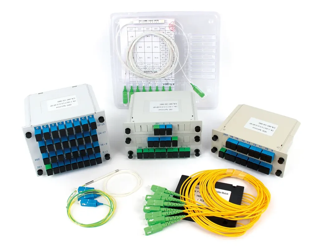
Figure 1: Fiber Optic Splitter
In a typical FTTX network, a single OLT port often needs to serve 16, 32, or even 64 users at the same time.
Instead of deploying one fiber per user (which would be extremely costly and inefficient), networks rely on a passive device to distribute optical signals efficiently — the fiber optic splitter.
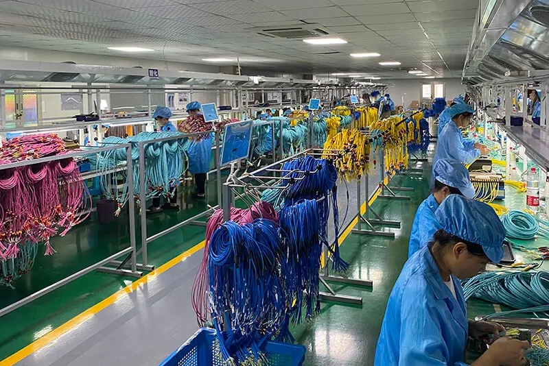
As a fiber optic splitter manufacturer, we’ve worked with telecom contractors, system integrators, and distributors across different deployment scenarios — from small FTTH installations to large-scale GPON and XGS-PON networks.
And in real projects, we’ve seen a common pattern:
Most people don’t struggle with what a splitter is, but with questions like:
- How do I choose between PLC and FBT?
- What do these parameters actually mean?
- Why does my power budget fail after installation?
- Which packaging type should I use?
In this guide, we’ll break down PLC splitters from a practical, engineering-focused perspective — combining manufacturing insights with real-world deployment experience.
What Is a Fiber Optic Splitter?
A fiber optic splitter is a passive optical device that divides a single optical signal into multiple outputs.
In simple terms, it allows one fiber input to serve multiple endpoints — without requiring any power supply.
Where It Sits in the Network

Figure 2: Fiber Optic Splitter use in PON
In a Passive Optical Network (PON), the splitter is typically located in the Optical Distribution Network (ODN), between:
- The OLT (Optical Line Terminal)
- And multiple ONUs (Optical Network Units)
Think of it like a water distribution system:
One main pipeline (fiber input) is split into multiple smaller pipelines (outputs), each delivering signal to a different user.
Why It Matters in Real Deployments
Without splitters, every user would require a dedicated fiber from the OLT — which is not scalable.
In real FTTX deployments:
- A 1×32 splittercan reduce fiber usage by up to ~90%
- Network construction cost can drop by 30–50%
- Cable routing complexity is significantly reduced
That’s why splitters are not just components — they are a core building block of scalable optical access networks.
Understanding Splitter Technologies
In practice, there are three main technical approaches:
- FBT (Fused Biconical Taper)— often called couplers
- PLC (Planar Lightwave Circuit)
- Micro-optic splitters (free-space optics)
FBT Splitter (Coupler)
FBT splitters are made by fusing and tapering optical fibers together.
Their key characteristics:
- Can achieve non-uniform split ratios(e.g. 1:99, 20:80)
- Lower cost for small channel counts
- Performance depends heavily on wavelength
👉 In real use: FBT is often used in special coupling scenarios, not large-scale PON networks.
Micro-Optic Splitter
Micro-optic splitters use lenses, mirrors, and free-space optical paths to distribute light.
Typical features:
- Flexible optical design
- Can support complex optical paths
- Often used in high-end or specialized optical systems
👉 However, they are generally more complex and expensive, and not the mainstream choice for FTTX deployments.
PLC Splitter (Mainstream Technology)
PLC splitters use planar waveguide technology on a silica substrate, allowing:
- Uniform signal splitting
- Full wavelength operation (1260–1650 nm)
- High stability and scalability
👉 This is why: In most modern GPON, XGS-PON, and FTTX networks, PLC splitters are the standard choice.
PLC vs FBT: Which One Should You Use?
Although both PLC and FBT are optical splitters, their performance and applications differ significantly.
Feature | PLC Splitter | FBT Splitter |
Technology | Planar waveguide | Fused fiber |
Wavelength Range | 1260–1650 nm | Limited |
Power Distribution | Uniform | Customizable |
Stability | High | Moderate |
Temperature Sensitivity | Low | Higher |
Typical Use | GPON / FTTX | Special couplers |
How to Decide (From Real Projects)
In most real-world deployments:
- FTTH / FTTB / FTTA
- GPON / XGS-PON networks
You should choose PLC splitters, because they provide:
- Stable performance across all wavelengths
- Consistent signal distribution
- Better long-term reliability
When FBT Still Makes Sense
FBT is still useful when:
- You need uneven splitting ratios
- You’re working on test systems or lab setups
- You’re dealing with legacy network designs
Simple Rule
- Standard telecom deployment → PLC
- Special ratio requirement → FBT
How a PLC Splitter Works

Figure 3: Understand Splitter key Structure
From the outside, a PLC splitter looks simple. But internally, its performance depends on a combination of optical design and manufacturing precision.
A PLC splitter is mainly composed of three core components:
- Pigtail fibers (input/output)
- Fiber Array (FA)
- PLC chip
These components are precisely aligned, bonded, and packaged to form a complete optical device.
Pigtail (Input/Output Fibers)
The pigtail fibers are fixed inside a glass capillary and polished at an angle (typically around 8°).
Why angled polishing matters:
- Reduces back reflection
- Improves return loss (typically ≥ 55 dB)
👉 In simple terms: It prevents the signal from “bouncing back” and interfering with the system.
Fiber Array (FA)
The fiber array uses a V-groove structure to precisely align multiple fibers.
This ensures:
- Accurate channel spacing
- Stable optical coupling
Even a few microns of alignment deviation can:
- Increase insertion loss by 2–0.5 dB
- Cause noticeable performance degradation in high split ratios
PLC Chip (Core Component)
The PLC chip is the heart of the splitter.
It is fabricated on a silica substrate using processes such as:
- PECVD
- Ion exchange
Inside the chip, optical waveguides are designed to:
- Split one input signal into multiple outputs
- Maintain uniform power distribution
Why Manufacturing Precision Matters
On paper, many PLC splitters look identical. But in real deployments, performance depends on:
- Alignment accuracy
- Polishing quality
- Epoxy control
- Optical testing
👉 That’s why: Two splitters with similar specifications can behave very differently in the field.
Uniform vs Unequal PLC Splitters
PLC splitters are widely known for uniform power distribution — for example, a 1×8 splitter ideally distributes optical power equally across all 8 outputs.
However, in recent years, unequal (asymmetric) PLC splitters have started to appear in the market, especially in more advanced network designs.
What’s the Difference?
Type | Power Distribution | Typical Use |
Uniform PLC | Equal split (e.g. 12.5% each for 1×8) | Standard PON / FTTX |
Unequal PLC | Custom ratios (e.g. 10%, 20%, 70%) | Chain / Bus topology |
Why Unequal PLC Splitters Are Used
In some network designs — especially bus or chain topology deployments — not all endpoints are at the same distance.
For example:
- Users closer to the OLT require less optical power
- Users further away need more signal margin
In this case:
Using a uniform splitter may lead to: Near-end signal waste/ Far-end signal instability
Unequal PLC splitters solve this by:
- Allocating more power to distant nodes
- Reducing unnecessary signal allocation to nearby users
From Practical Experience
While unequal PLC splitters are useful, they are still:
- Less standardized
- More application-specific
So in most projects:
- Uniform PLC splitters remain the default choice
- Unequal splitters are used only when network design requires fine power balancing
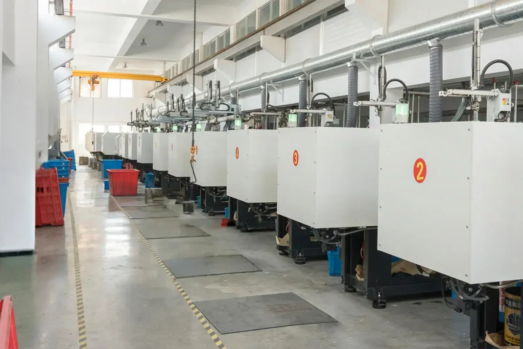
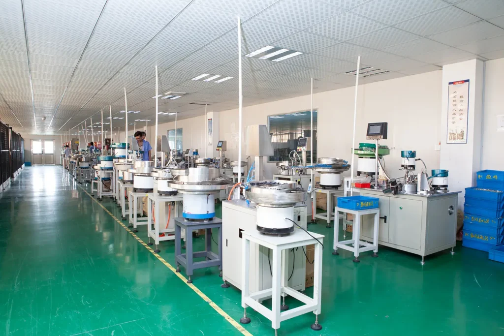
PLC Splitter Manufacturing Process
While the core structure of a PLC splitter is relatively straightforward, its manufacturing process is highly detail-driven.
The production of pigtails and fiber arrays (FA) belongs to standard component processes. Across different manufacturers, the overall workflow is generally similar — but the real difference lies in process control, precision, and automation level.
Once the three key components — pigtail, FA, and PLC chip — are prepared, the assembly of a PLC splitter typically follows an industry-standard process, including:
- Component alignment and positioning
- Optical active alignment (input/output tuning)
- UV adhesive dispensing and fixing
- Fine adjustment (micro-alignment)
- UV curing
- End-face inspection
- Packaging and sealing
- Reliability testing
From our manufacturing experience, each step directly impacts the final performance of the device.
For example:
- Poor alignment → higher insertion loss
- Inconsistent UV curing → long-term instability
- Surface contamination → degraded return loss
👉 In simple terms:
PLC splitter manufacturing is not about “complex steps”, but about how well each detail is controlled.

Figure 4: Undertand PlC Splitter manufacturing process
The diagram shows a typical PLC splitter manufacturing flow used in the industry.
While different factories may have variations in automation and process control, the core steps remain largely consistent.
Key Specifications You Should Understand
When you look at a PLC splitter datasheet, it can feel overwhelming. But in practice, you only need to focus on a few key parameters.
Insertion Loss (IL)
This is the most critical parameter.
It measures how much optical power is lost during splitting.
Uniformity
Uniformity measures how evenly power is distributed across outputs.
Return Loss (RL)
Return loss indicates how much light is reflected back toward the source.
Polarization Dependent Loss (PDL)
PDL measures how signal loss varies with polarization.
Operating Temperature
It defines whether the splitter can work reliably in outdoor or harsh environments.
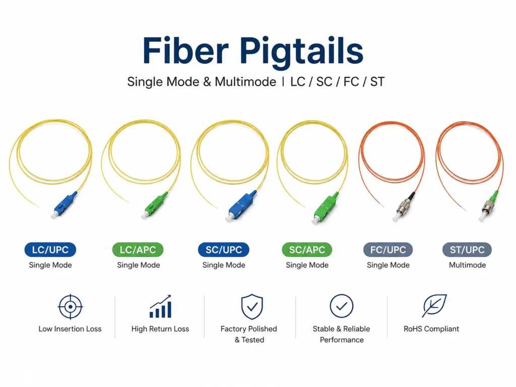
Packaging Types and Where They Are Used
One thing that often confuses users is this: Why are there so many different splitter types in the market?
The answer is simple: The core PLC splitter doesn’t change — the packaging does.
Different packaging is designed to match different installation environments.

Figure 5: Fiber Optic splitter packing types
Common Packaging Types
Bare Fiber Splitter
- No external housing
- Smallest size
- Used inside splice closures
In real deployments: This is commonly used in underground closures or fiber splice boxes, where space is limited.
Mini Module (Steel Tube Type)
- Compact metal tube packaging
- Fiber protected inside
Typical use: Widely used in FTTX distribution points and ODN nodes
Box Type Splitter
- Plastic or ABS box
- Better mechanical protection
Suitable for: Outdoor cabinets, Wall-mounted boxes
Cassette / LGX Module
- Standardized size
- Plug-and-play design
Typical use: Central office racks / Data center environments
Rack-Mount Splitter
- Installed directly in 19-inch racks
- High-density deployment
How to Think About It
When you choose a splitter, don’t just think about “1×8 or 1×32”. You should ask:
- Where will this be installed?
- Is it indoor or outdoor?
- Does it need mechanical protection?
- Will it be frequently accessed?
👉 Because in real projects, wrong packaging causes more problems than wrong parameters.
Reliability and Standards: What Really Matters
On paper, many splitters look similar. But long-term reliability is where the real difference shows up.
Key Industry Standards
Most high-quality PLC splitters follow:
- GR-1209-CORE→ General requirements
- GR-1221-CORE→ Reliability requirements
These standards are widely recognized in global telecom networks.
Typical Reliability Tests
A qualified PLC splitter should pass tests such as:
- 2000 hours damp heat test
- 2000 hours high/low temperature storage
- Thermal cycling (20+ cycles)
- Mechanical shock and vibration
- Cable tensile test (≥ 70N)
- Water immersion test
- Salt fog test
👉 In simple terms: These tests simulate years of real-world usage in harsh environments.
From Manufacturing Experience
In our experience, failures in the field are rarely caused by:
- “wrong theory”
- They are usually caused by:
- Poor sealing
- Weak fiber protection
- Inconsistent epoxy curing
- Low-quality polishing
👉 That’s why: Even if two splitters have the same datasheet, their long-term performance can be completely different.
How to Choose the Right PLC Splitter
This is where most real-world issues happen. Instead of just picking a random split ratio, you should think systematically.

Figure 6: Know how to choose fiber splitter
From Manufacturing Experience
Start with your link budget. For example:
- GPON typical budget: 28 dB (Class B+)
- XGS-PON: 29–31 dB
Then subtract:
- Fiber attenuation
- Connector loss (~0.2–0.5 dB per connector)
- Splice loss (~0.1 dB per splice)
- Splitter insertion loss
👉 Practical tip: If your margin is too tight, don’t jump directly to 1×32 or 1×64.
Based on Deployment Density
From real FTTX projects:
- Rural areas → 1×8 or 1×16
- Suburban → 1×16 or 1×32
- Urban high-density → 1×32 or 1×64
Why?—Because user density determines how much splitting you actually need.
Based on Installation Environment
Ask yourself:
- Indoor or outdoor?
- Underground or cabinet?
- Temperature extremes?
Example: Outdoor → must support -40°C to +85°C
High humidity → sealing quality matters more than specs
A Simple Selection Logic
Ask yourself:
- Indoor or outdoor?
- Underground or cabinet?
- Temperature extremes?
Example: Outdoor → must support -40°C to +85°C
High humidity → sealing quality matters more than specs
Based on Connector Type
Common connectors:
- SC/APC
- LC/APC
Practical advice: Always match your splitter connectors with your network design. Mismatched connectors = unnecessary loss.
Common Mistakes to Avoid
One of the most common issues we hear from customers is: “The design looks correct, but the signal still doesn’t work after installation.”
In most cases, this isn’t caused by a single mistake — but by multiple small losses that were underestimated or ignored during planning.
Start with a Simple Power Budget
In a typical PON system, total link loss can be estimated as:
Total Loss = Splitter Loss + Connector Loss + Fiber Attenuation + Splice Loss
Example (Realistic Scenario):
Item | Value |
Splitter (1×32) | ~17 dB |
Connectors (4 × 0.3 dB) | ~1.2 dB |
Fiber (10 km × 0.35 dB/km) | ~3.5 dB |
Splice Loss (5 × 0.1 dB) | ~0.5 dB |
Total Loss | ~22.2 dB |
If your system budget is 28 dB, the theoretical margin is: 28 – 22.2 = 5.8 dB
At first glance, this looks safe. But in real deployments, additional losses often come from:
- Connector contamination
- Fiber bending
- Installation inconsistencies
These can easily consume another 2–5 dB, pushing the system close to failure.
Where Things Usually Go Wrong
From our experience across multiple projects, power budget failures are usually linked to a few common issues:
1. Ignoring Connector Loss
Many designs only consider splitter loss, but in reality: Each connector typically adds 0.2–0.5 dB
With multiple connection points, this becomes a major hidden loss.
2. Choosing an Overly High Split Ratio
It’s tempting to use higher split ratios like 1×64 to reduce cost. But in practice:
- Higher split = higher insertion loss
- Lower signal margin
- Increased risk of ONU instability
3. Underestimating Installation Impact
Even if the design is correct, poor installation can break the system.
Common examples:
- Fiber bending radius too small
- Poor cable routing
Mechanical stress on fibers
4. Connector and Adapter Issues
A very common but overlooked problem:
- Mixing SC/APC and SC/UPC
- Poor connector quality
- Dirty end faces
These can introduce unexpected attenuation and reflections.
5. Environmental Factors
Especially in outdoor deployments:
- Moisture ingress
- Temperature fluctuation
- Poor sealing
Over time, these degrade performance significantly.
Quick Troubleshooting Reference
Symptom | Likely Cause | What You Should Check |
Weak signal | Excessive splitting | Recalculate split ratio |
Sudden high loss | Fiber bending | Check routing radius |
Unstable signal | Dirty connectors | Clean end faces |
Unexpected attenuation | Connector mismatch | Verify APC vs UPC |
Gradual degradation | Environment exposure | Check sealing / enclosure |
Uneven signal | Poor uniformity | Verify splitter quality |
A Practical Takeaway
When troubleshooting a failed link:
Don’t focus only on the splitter — always evaluate the entire optical path.
Because in most real-world cases:
👉 The issue is not the splitter itself
👉 It’s the combination of design assumptions and installation details
Frequently Asked Questions
What is the difference between a PLC splitter and an FBT splitter?
The main difference lies in technology and application.
PLC splitters use planar waveguide technology and support a full wavelength range (1260–1650 nm), making them ideal for modern GPON and XGS-PON networks. They also provide uniform power distribution across all outputs.
FBT splitters, on the other hand, are made by fusing optical fibers and are more suitable for custom split ratios (like 20:80 or 1:99). However, they are more sensitive to wavelength and environmental conditions.
In most FTTX deployments, PLC splitters are the preferred choice.
How do I choose between 1×8, 1×16, and 1×32 splitters?
The choice depends mainly on your power budget and user density.
- 1×8 or 1×16 → suitable for rural or low-density areas
- 1×32 → commonly used in standard FTTH deployments
- 1×64 → used in high-density urban networks (but requires careful power budget calculation)
A higher split ratio reduces infrastructure cost but increases insertion loss, so always calculate your link budget before deciding.
What causes high loss in a fiber optic splitter link?
High loss is usually not caused by a single factor, but a combination of multiple issues, such as:
- High split ratio (e.g. 1×64)
Connector loss (typically 0.2–0.5 dB per connector)
Fiber attenuation over long distances
Dirty or damaged connectors
Fiber bending or poor installation
In practice, installation quality often has a bigger impact than the splitter itself.
Are all PLC splitters the same if the specifications look identical?
Not necessarily. Even if two PLC splitters have similar datasheet specifications, their real-world performance can differ due to:
- Alignment precision during manufacturing
- Fiber array quality
- Polishing and end-face quality
- Adhesive and packaging process
- Testing standards (e.g. Telcordia compliance)
This is why reliability and consistency often depend on the manufacturer, not just the specs.
Can PLC splitters be used in outdoor environments?
Yes — but only if they are properly designed for outdoor use. You should check:
- Operating temperature range (typically -40°C to +85°C)
- Sealing and protection level
- Packaging type (e.g. box type or outdoor closure integration)
Using indoor-grade splitters in outdoor environments can lead to moisture ingress, signal degradation, and early failure.
Conclusion
PLC splitters have become the standard solution in modern optical networks — not just because of theory, but because they perform reliably in real deployments.
From the core structure and manufacturing precision, to parameter selection and packaging design, every detail affects how the splitter behaves in the field.
From our experience working with different FTTX and PON projects, the most successful deployments are not the ones using the “highest specs”, but the ones using the right configuration based on real conditions.
If you’re currently evaluating splitters for your network, or trying to optimize your design: We’re always happy to share practical recommendations based on your specific deployment scenario — whether it’s split ratio selection, packaging, or power budget planning.