If you’re just stepping into the world of fiber optics, all the technical terms and abbreviations can feel overwhelming. That’s why I created this fiber glossary series — to help you understand what these terms really mean, in the simplest way possible.
TABLE OF CONTENTS
Introduction
In the previous article, we talked about insertion loss — the portion of light that fails to reach the destination as it passes through connectors, splices, and other components in a fiber optic link.
But there is another question that naturally follows: If some of the light doesn’t move forward, where does it go?
In many cases, that light doesn’t simply disappear. Instead, it reflects backward, traveling in the opposite direction toward the light source. This backward reflection is described by a parameter known as RL(return loss).
While insertion loss focuses on how much light is lost along the path, return loss tells a different story — how much light is sent back toward the transmitter. In modern fiber optic systems, especially high-speed and long-distance links, this distinction matters more than many people realize.
Return Loss: What It Really Describes
Return loss measures the amount of optical power that is reflected back toward the source due to imperfections in the fiber link.
Rather than thinking of return loss as just another specification, it helps to view it as a sign of how “clean” a connection really is. A good connection allows light to move forward with minimal reflection. A poor one acts like a tiny mirror, sending part of the signal back.
There is an important contrast worth keeping in mind:
- Insertion lossis about light that fails to reach the receiver
- Return lossis about light that turns around and heads back to the transmitter
Both describe loss, but they reveal different problems. A connection can show acceptable insertion loss while still having poor return loss — a situation that often leads to unstable or noisy systems.
Why Light Reflects in Fiber Optic Systems
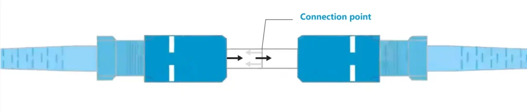
In theory, optical fibers guide light smoothly along the core. In practice, every connection introduces an interface, and every interface creates an opportunity for reflection.
At a basic level, reflection occurs whenever light encounters a change in refractive index. In fiber systems, that usually means transitions between glass and air or between slightly mismatched materials. These transitions are unavoidable, but their effects can be minimized — or amplified — depending on installation quality.
Several real-world factors play a role.
Air Gaps at Fiber Interfaces

When two fiber end faces do not make perfect physical contact, even a microscopic air gap can cause strong reflection. At the glass–air boundary, part of the light is reflected backward instead of continuing forward.
This is one of the most common causes of high return loss, and it often appears together with increased insertion loss.
End-Face Quality and Surface Damage
Scratches, pits, or uneven polishing on a fiber end face scatter light in unpredictable directions. Some of that scattered light reflects directly back toward the source.
Even connectors that look fine to the naked eye can produce significant reflection when viewed under a fiber inspection scope.
Connector Type and End-Face Geometry
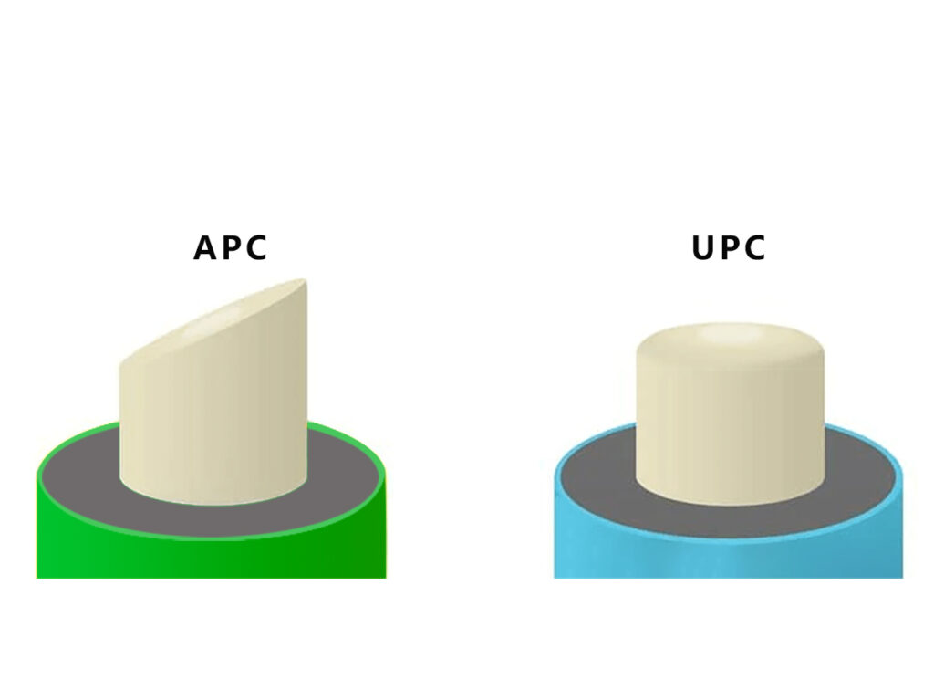
The geometry of a connector’s end face has a direct impact on return loss.
PC and UPC connectors rely on flat or slightly curved surfaces, which can still reflect light back along the same path. APC connectors, on the other hand, introduce a small angled polish that redirects reflected light away from the fiber core.
This is why APC connectors are widely used in applications where reflection must be tightly controlled.
Contamination: A Small Problem with Big Effects
Dust, oil, or residue on a connector end face can dramatically increase return loss. In fact, return loss is often more sensitive to contamination than insertion loss.
A link may still pass insertion loss testing while suffering from poor return loss simply because the reflected light does not significantly reduce forward power — but it does destabilize the transmitter.
Why Return Loss Matters More Than Many People Expect
Backward-reflected light does more than reduce signal quality. In laser-based systems, it can interfere directly with the light source itself.
When reflected light re-enters a laser, it can cause:
- Increased noise and signal fluctuation
- Laser instability and wavelength drift
- Higher bit error rates in digital systems
These effects are especially noticeable in:
- High-speed data center links
- PON and FTTH networks
- Analog optical systems such as CATV
In many cases, a network that appears to “work” may still experience intermittent issues because return loss was never properly addressed.
Measuring Return Loss in Practice
Return loss is typically measured using instruments such as an OTDR or a dedicated optical return loss (ORL) meter. These tools evaluate how much of the launched light is reflected back toward the source.
The basic expression for return loss is:
RL (dB) = −10 × log₁₀ (Preflected / Pin)
One detail often confuses beginners: higher return loss values indicate better performance. This is the opposite of insertion loss, where lower values are better.
A higher return loss means less reflected power and a cleaner optical link.
What Is Considered a “Good” Return Loss?
Acceptable return loss values depend on fiber type, connector design, and application requirements.
Single-mode systems generally demand tighter control of reflections than multimode systems due to longer transmission distances and more sensitive light sources. If this distinction is new to you, Fiber Optic: Single Mode vs Multimode – What’s the Difference? offers a useful introduction.
As a general trend:
- APC connectors provide the best return loss performance
- UPC connectors perform better than standard PC connectors
- Applications like FTTH often specify APC to minimize reflection
And if you have some question about APC and UPC, this article might be helpful to you: Fiber Optic APC vs UPC – What’s the Real Difference?
In multi-fiber environments, such as MPO and MTP connections, maintaining consistent return loss across all fibers becomes more challenging due to alignment complexity and end-face variation.
Field Tips: Reducing Return Loss in Real Installations
Experienced technicians tend to follow a few practical rules.
Cleaning comes first. Before assuming a connector or component is defective, both end faces should be thoroughly cleaned using lint-free wipes or fiber cleaning pens.
Inspection follows cleaning. Visual inspection helps identify scratches, chips, or contamination that cleaning alone cannot fix.
Finally, connector selection matters. Using APC connectors in reflection-sensitive systems often solves problems that no amount of troubleshooting can fix later.
These steps may seem simple, but they prevent a large percentage of return loss issues encountered in the field.
Closing Thoughts
Return loss describes what happens to the light that doesn’t continue forward — and in many systems, that backward-traveling light is just as important as the power that reaches the receiver.
Together, insertion loss and return loss provide a more complete picture of fiber optic link quality. One shows how much signal is lost along the way; the other reveals how much is reflected back.
Understanding both allows engineers and installers to build fiber networks that are not only functional, but stable, reliable, and ready for high-speed operation.
Still Have Questions?
If you’re still unsure about something, feel free to reach out.
Want to explore more fiber optic terms? Head over to our blog section.
If the term you’re looking for isn’t covered yet, let me know — I’ll add it to the priority list!
And lastly — if you’re a telecom provider, network operator, or involved in fiber infrastructure development and looking for a reliable partner in fiber optic components — feel free to contact us.