In the world of fiber optic communication, light travels through strands of glass thinner than a human hair, carrying massive amounts of data across long distances. But just like water flowing through a pipe, not all of the light reaches its destination perfectly. Along the way, some of it leaks out, and some of it bounces back in the wrong direction. In fiber optics, these two effects are known as insertion loss (IL) and return loss (RL).
For beginners trying to understand fiber optic performance, IL and RL can seem like intimidating technical terms. However, once we break them down with real-world analogies and simple math, they become much easier to grasp. And understanding them is essential, because they directly affect how well a fiber optic link performs, how reliable internet connections are, and even how network engineers design and test communication systems.
Today, we’re going to talk about: IL( insertion loss) and RL(return loss)
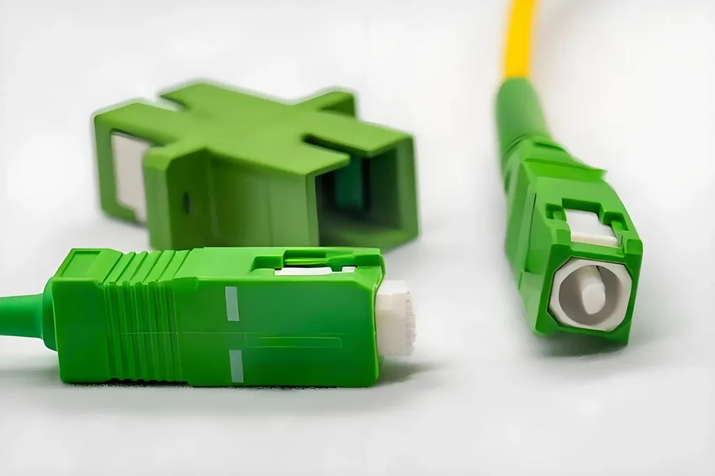
TABLE OF CONTENTS
What Is Insertion Loss (IL)?
Insertion loss is the reduction of optical power as light travels through a fiber component. Whenever you insert something into the optical path — a connector, a splice, or even a test device — a small portion of the signal is lost. This reduction is measured in decibels (dB), with lower numbers being better. Ideally, insertion loss would be zero, but in the real world, every component introduces a little bit of loss.
Think of insertion loss like water leaking out of a pipe. If you attach two pipes together, the joint isn’t perfectly sealed, and a small amount of water may escape. Similarly, when two fiber ends are joined, even the most carefully polished connectors can allow a fraction of the light to escape.
Typical values for insertion loss vary depending on the component:
- A well-made connector might have an IL of around 0.2–0.5 dB.
- A fusion splice, where fibers are melted together, might be as low as 0.05 dB.
- Mechanical splices or poor-quality connectors can result in higher IL, up to 0.75 dB or more.
From a mathematical perspective, insertion loss is calculated as:
IL (dB) = 10 × log₁₀ (P_in / P_out)
where P_in is the power launched into the component, and P_out is the power received at the other side.
For example, if a laser launches -3 dBm of power and the detector measures -5.5 dBm after passing through connectors and fiber, the insertion loss is 2.5 dB. Even this small difference matters, because excessive IL across a network can reduce signal strength below acceptable limits.
What Is Return Loss (RL)?
While insertion loss describes light that escapes, return loss describes light that bounces back in the wrong direction. In fiber optics, whenever light encounters a boundary — such as the interface between a connector and air, or a slightly misaligned fiber core — some of it reflects backward toward the source. This reflected light is measured as return loss.
Here’s where it can get a little confusing: higher return loss values are better. Why? Because return loss is expressed as a positive number that represents how much stronger the original signal is compared to the reflected signal. A return loss of 60 dB means the reflection is extremely small, while a return loss of 20 dB means a much stronger reflection.
The formula looks like this:
RL (dB) = -10 × log₁₀ (P_reflected / P_in)
The negative sign is there to make the result positive, but in practice, we simply talk about RL in positive dB values — higher numbers mean less reflection, which is what we want.
A helpful analogy is shouting into a canyon. If you hear a strong echo, it’s difficult to focus on the original message. If the echo is faint or nonexistent, communication is much clearer. In fiber optics, reflections can interfere with laser sources, distort signals, and increase error rates. That’s why connectors with angled physical contact (APC connectors) are widely used; their angled surfaces direct reflected light away, typically achieving return loss values of -60 dB or better.
IL vs RL – Two Sides of the Same Story
Although insertion loss and return loss measure different effects, they are closely related. Both determine how effectively light travels through a fiber optic link.
- Insertion Loss (IL): How much signal is lost in transmission. Lower is better.
- Return Loss (RL): How much signal bounces back. Higher is better.
To make this clearer, here’s a quick comparison:
| Aspect | Insertion Loss (IL) | Return Loss (RL) |
|---|---|---|
|
What it measures |
Light lost going forward |
Light reflected backward |
|
Ideal value |
As close to 0 dB as possible |
As high as possible (>40–60 dB) |
|
Impact |
Reduces received signal power |
Adds noise and potential errors |
|
Analogy |
Water leaking out of a pipe |
Echo bouncing back when you shout |
Understanding this balance helps network designers and installers evaluate fiber optic performance. A good connector or splice will have low IL and high RL, ensuring the signal arrives strong and clean.
Why IL and RL Matter in Fiber Optic Networks
At first glance, losing 0.5 dB of power here and 0.75 dB there might not seem like much. But in a large passive optical network (PON) or a data center with hundreds of connections, these small losses add up quickly. If the total insertion loss in a link exceeds the network’s link budget — the maximum allowable loss for reliable operation — users may experience slow internet speeds, dropped connections, or even complete outages.
Return loss is equally important. Too much reflected light can destabilize laser sources, especially in high-speed systems such as 10G, 40G, or 100G Ethernet. Reflections also increase noise and can trigger nonlinear effects in long-haul fiber transmission. In short, poor return loss values compromise the stability of the entire network.
This is why industry standards such as TIA/EIA and IEC specify limits. For example, connectors are often required to have IL less than 0.75 dB and RL greater than 40 dB. High-performance APC connectors may reach RL values of 60 dB or more, providing superior performance in demanding applications.
How IL and RL Are Measured

In practice, IL and RL are not just theoretical concepts. Network engineers and technicians routinely test them during installation and maintenance to ensure a fiber link is within specifications.
For insertion loss, the most common test is called the loss test. A stable light source is connected at one end of the link, and an optical power meter measures the output at the other end. By comparing the input and output power, the technician calculates the IL of the entire link.
For return loss, testing is a bit more complex, because it involves measuring reflections. Specialized devices such as optical return loss meters or OTDRs (Optical Time Domain Reflectometers) are used. An OTDR, in particular, is extremely useful because it not only measures overall return loss but also shows the exact location of reflections along the fiber. If a connector is dirty or a splice is misaligned, the OTDR trace will reveal the spike, making troubleshooting much easier.
These measurements are crucial in fields such as data centers, where hundreds of connections must be tested, or in telecom networks, where miles of fiber must meet strict standards before being put into service.
Common Causes of High IL and Poor RL
While high-quality fiber components are designed to minimize loss and reflection, problems can still occur in the field. Some common causes include:
- Dirty or scratched connectors: Dust or fingerprints on the endface can significantly increase both IL and RL.
- Poor splicing technique: Misaligned or improperly fused fibers allow light to scatter.
- Excessive bending: Tight bends in fiber cables cause microbending losses and reflections.
- Low-quality components: Cheap connectors and adapters often fail to meet international standards.
- Improper installation: Failing to use protective closures or strain relief can damage fibers over time.
Fortunately, many of these issues are preventable with good practices: proper cleaning, correct handling, and using reliable components.
IL and RL in Real-World Applications
To appreciate why IL and RL matter, let’s look at a few practical scenarios:
- Fiber to the Home (FTTH) / Passive Optical Networks (PON)
In a PON system, one OLT serves dozens or even hundreds of customers through passive splitters. Each splitter introduces its own insertion loss, so engineers must carefully calculate the total loss budget to ensure that even the farthest customer receives enough signal. Return loss also matters, as reflections could destabilize the shared light source. - Data Centers
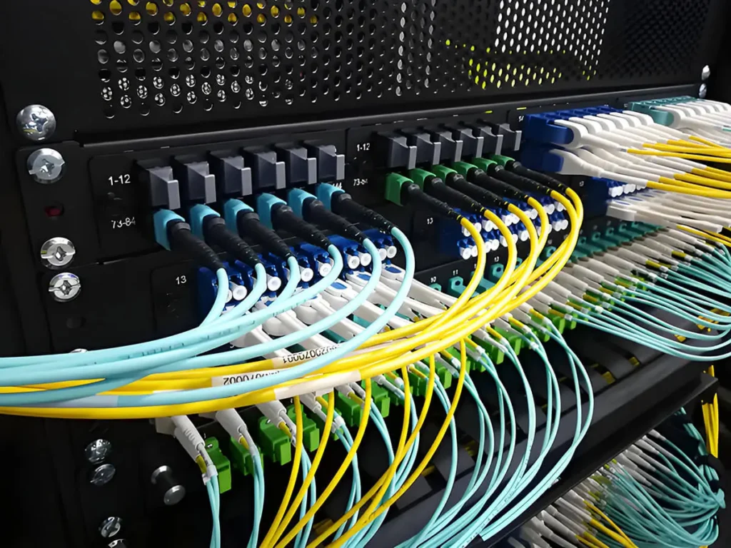
Modern data centers rely on high-density fiber cabling, often with multiple patch panels, MPO/MTP connectors, and cross-connects. Even small amounts of extra IL per connection can quickly add up, jeopardizing high-speed links such as 40G and 100G Ethernet. Return loss is also critical, since reflected signals can degrade sensitive transceivers. - Long-Haul and Metro Networks
Over hundreds of kilometers, cumulative IL must be kept under strict limits to avoid the need for excessive amplification. Meanwhile, return loss must be minimized to prevent interference with coherent detection systems used in advanced long-haul transmission.
In all of these cases, controlling IL and RL is not just about meeting technical specifications; it’s about ensuring stable, reliable, and future-proof communication.
How Manufacturers Help Control IL and RL
Behind every fiber network are thousands of components — connectors, adapters, splitters, patch cords, closures, and panels. Each one contributes a fraction to the overall insertion and return loss. This is why component quality is so important.
At YingFeng Communication, we specialize in producing fiber optic accessories with low IL and high RL performance, meeting or exceeding GR-326 and other international standards. Our portfolio includes:
- Fiber optic connectors and adapters with precision polishing
- Patch cords and pigtails designed for minimal insertion loss
- Splitters and closures engineered for stable performance
- Patch panels (ODF) for structured, low-loss cabling
For network operators, ISPs, or system integrators, choosing reliable components is the foundation for building efficient and stable networks.
FAQ: Insertion Loss and Return Loss
What is considered a good insertion loss value?
Generally, insertion loss should be less than 0.75 dB per connector. Fusion splices often achieve below 0.1 dB.
What is considered a good return loss value?
For single-mode fiber connectors, an RL of ≥40 dB is acceptable. High-performance APC connectors can reach ≥60 dB, which is excellent.
Why is return loss expressed as a positive number even though it’s technically negative?
By convention, RL is reported as a positive dB value. A higher RL means lower reflection, which makes interpretation simpler.
Can dirty connectors affect both IL and RL?
Yes. Dirt and dust are among the leading causes of high insertion loss and poor return loss. That’s why connector cleaning is standard practice during installation.
How do IL and RL impact high-speed systems like 100G or 400G Ethernet?
At higher speeds, the margin for error is smaller. Even small amounts of extra IL can push the link budget over the limit, and reflections can destabilize advanced transceivers. This makes precise IL/RL control more critical than ever.
In Summary
Insertion loss and return loss are two of the most fundamental performance parameters in fiber optics. IL tells us how much signal is lost as light travels through components, while RL tells us how much light is reflected back toward the source. Together, they determine whether a fiber link is strong, clean, and reliable.
For beginners, it helps to think of IL as water leaking out of a pipe, and RL as echoes bouncing back when you shout in a canyon. In both cases, minimizing these effects ensures smoother communication.
As fiber networks expand into homes, businesses, and data centers, understanding IL and RL has never been more important. And behind every reliable network are the components that make it possible. At YingFeng Communication, we are proud to provide the connectors, adapters, patch cords, and distribution products that keep insertion loss low, return loss high, and networks running at their best.
Still Have Questions?
If you’re still unsure about something, feel free to reach out.
Want to explore more fiber optic terms? Head over to our blog section.
If the term you’re looking for isn’t covered yet, let me know — I’ll add it to the priority list!
And lastly — if you’re a telecom provider, network operator, or involved in fiber infrastructure development and looking for a reliable partner in fiber optic components — feel free to contact to us.