As data centers grow in scale and the demand for bandwidth surges with 5G, AI, and cloud computing, traditional single-fiber or duplex connectors can no longer keep up. High-density, high-speed cabling solutions have become essential.
In particular, AI-driven data centers—built around large-scale GPU clusters and parallel optical architectures—rely heavily on MPO connectivity to achieve extreme fiber density, low latency, and scalable network expansion.
One of the most important technologies enabling this shift is the MPO connector (Multi-fiber Push On). By housing multiple fibers in a single compact interface, MPO connectors dramatically increase connectivity density and simplify cabling. They are now widely used in data centers, FTTX networks, and parallel optical transmission systems to support 40G, 100G, 400G, and beyond.
TABLE OF CONTENTS
Why MPO Connectors Are Critical in AI Data Centers
Modern AI data centers and hyperscale facilities are fundamentally different from traditional enterprise networks. Large-scale AI workloads depend on GPU clusters that exchange massive volumes of data in parallel, placing extreme demands on bandwidth, latency, and cabling density.
MPO connectors address these challenges by enabling parallel optical transmission within a compact footprint. Instead of managing dozens of duplex fiber links, data center operators can deploy MPO-based trunk and breakout architectures to support 40G, 100G, 400G, and emerging 800G interfaces more efficiently.
As AI computing continues to scale, MPO connectivity has become a foundational building block for high-density, future-ready data center infrastructure.
What is an MPO Connector?
The MPO connector is a multi-fiber optical connector defined by international standards IEC 61754-7 and TIA-604-5 (FOCIS-5). Unlike LC or SC connectors that terminate a single fiber, MPO can accommodate multiple fibers in one connector body, making it ideal for high-speed parallel transmission.
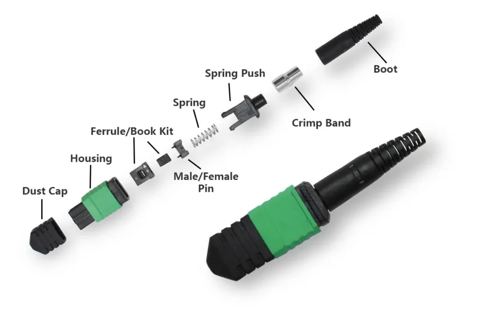
While the exterior of an MPO connector looks similar to other connectors, its internal structure is more sophisticated. It is composed of several precision-engineered parts, each serving a crucial role:
- Dust Cap – Protects the ferrule end face from dust, scratches, and contamination.
- Housing – Provides mechanical strength, protects the inner components, and ensures proper mating during plug-in/plug-out.
- Ferrule / Boot Kit – The heart of the connector, usually an MT ferrule, which aligns and secures multiple fibers in an array.
- Male/Female Pin Assembly – MPO connectors are available in male (with guide pins) and female (without guide pins) versions. The pins guarantee precise fiber alignment during mating.
- Spring – Maintains consistent pressure on the ferrule, ensuring low insertion loss and stable contact.
- Spring Push – Holds the spring in place and stabilizes the internal structure.
- Crimp Band – Secures the fiber to the boot, preventing cable movement or pull-out.
- Cable Boot – Provides bend protection at the cable entry point, reducing mechanical stress and extending service life.
The precision of custom-molded plastic components plays a critical role in MPO connector reliability, especially in high-density data center environments where mechanical tolerances are extremely tight.
Looking for reliable MPO solutions? Our factory manufactures high-quality MPO patch cords, ensuring low loss and stable performance. Learn more about our MPO Patch Cable.
MPO and the MT Ferrule
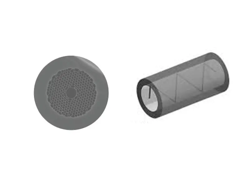
At the core of every MPO connector is the MT (Mechanical Transfer) ferrule. The MT ferrule is integrated inside the MPO connector and serves as its key component, enabling precise alignment of multiple fibers. Through the MT interface, MPO achieves high-density interconnection, most commonly in 12-fiber, 16-fiber, or 24-fiber formats.
Key characteristics of the MT ferrule include:
- Fiber Array: Fibers are precisely arranged in rows, with extremely tight tolerances.
- Guide Pins: Holes in the ferrule allow for guide pins to ensure alignment when mating male and female connectors.
- Material: Usually precision-molded thermoplastic with embedded fiber holes.
The alignment accuracy of the MT ferrule directly impacts insertion loss and return loss, making it one of the most critical elements in MPO performance.
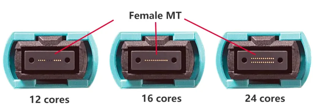
Fiber Counts in MPO Connectors
MPO connectors are available in several fiber counts. The most widely used configurations are:
- MPO-8: Supports four bidirectional channels, commonly used in 40G QSFP+ applications.
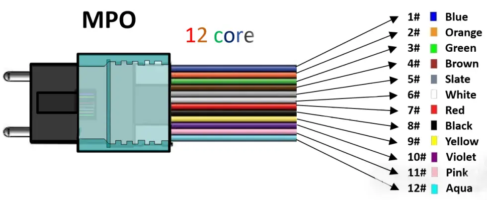
- MPO-12: The most common format, balancing density and cost-effectiveness. Each connector contains 12 fibers arranged in a single row.
- MPO-16: Supports emerging higher-speed applications such as 400G, where additional fibers are required for parallel transmission.
- MPO-24: Offers even greater density, with two rows of 12 fibers each, making it ideal for backbone connections in large data centers.
Higher-fiber-count MPOs (such as 32, 48, or 72) also exist, but the 8, 12, 16, and 24-fiber MPOs remain the most widely adopted in real-world deployments.
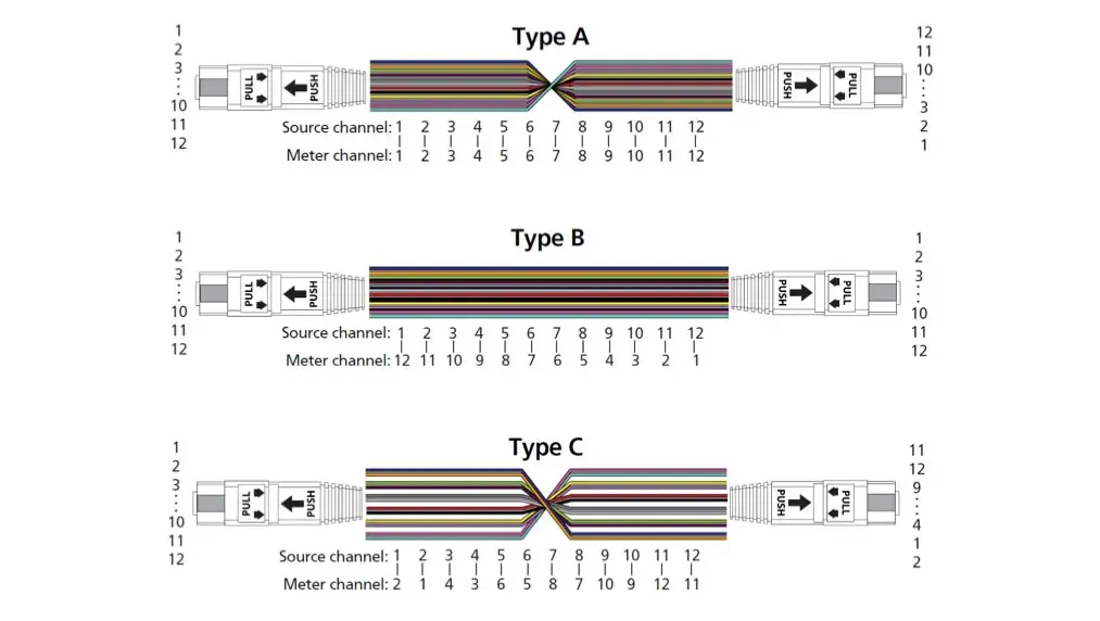
MPO Polarity (A, B, and C)
Unlike single-fiber connectors, MPO’s multi-fiber structure requires special consideration for polarity—ensuring that each transmit fiber correctly aligns with the corresponding receive fiber.
Three main polarity methods are defined:
- Polarity A (Straight-through) – Fiber 1 on one end connects to Fiber 1 on the other end, Fiber 2 to Fiber 2, and so on.
- Polarity B (Flipped) – The fiber order is completely reversed (Fiber 1 connects to Fiber 12, Fiber 2 to Fiber 11, etc.).
- Polarity C (Pairwise Flipped) – Fibers are flipped in pairs (1↔2, 3↔4, etc.), commonly used for duplex transmission systems.
Selecting the correct polarity is critical when deploying Polarity A/B/C MPO cables, as mismatched polarity will prevent proper signal transmission.
MPO vs. MTP
To understand the relationship between MPO and MTP, we first need to define each:
- MPO (Multi-fiber Push On) – the standardized multi-fiber connector defined by IEC 61754-7 and TIA-604-5. Earlier in this article, we already described MPO in detail.
- MTP (Multi-fiber Termination Push-on) – a high-performance version of the MPO connector, developed by US Conec. It improves on standard MPO designs by reducing insertion loss and return loss, making it more reliable for high-speed transmission.
From the outside, MPO and MTP connectors look almost identical, and they are fully compatible and interchangeable. However, internally, MTP features several engineering enhancements that lead to better optical and mechanical performance.
Key Differences Between MPO and MTP
| Feature | MPO (Standard) | MTP (Enhanced) |
|---|---|---|
|
Outer Housing |
Standard molded housing |
Removable housing, allowing for easier ferrule replacement |
|
Ferrule |
Standard MT ferrule |
High-performance MT ferrule with tighter tolerances |
|
Guide Pin |
Basic pin design |
Precision-machined pins with improved alignment accuracy |
|
Insertion Loss |
Higher (typically ~0.5 dB per connection) |
Lower (can achieve <0.35 dB typical per connection) |
|
Return Loss |
Standard compliance |
Enhanced polish quality for better return loss performance |
In short:
- MPO = the universal standard
- MTP = a premium MPO variant with improved optical and mechanical performance
For most data center applications, standard MPO is sufficient. But in ultra-high-speed systems (400G/800G), where low loss is critical, MTP connectors are often the preferred choice.
MPO Cable Connections
MPO connectors provide a versatile way to interconnect switches, transceivers, and distribution panels. Depending on the network requirements, MPO cables can be used in several configurations:
MPO to MPO Connections
An MPO to MPO cable can directly connect two switches equipped with SR multimode optical transceivers (QSFP, QSFP28, or QSFP-DD).
This architecture is widely adopted in AI data centers, where high-speed GPU interconnects require parallel optical links with minimal latency and maximum fiber density.
Typical Application: Data center switch-to-switch interconnects, high-speed backbone links, and parallel transmission environments (40G/100G/400G).
Advantage: Simplifies cabling by replacing multiple duplex connections with a single MPO trunk.

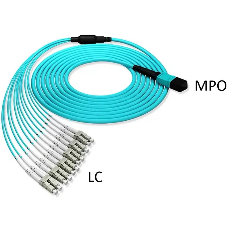
MPO to LC Breakout Connections
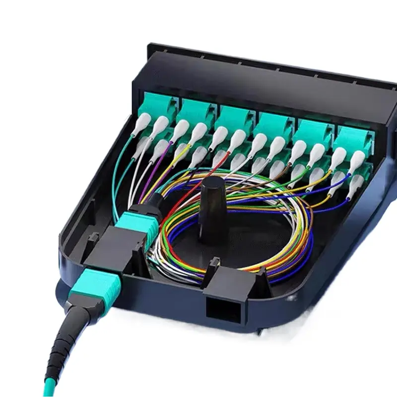
In many modern data center environments, especially those supporting AI and cloud workloads, network equipment may still rely on LC duplex interfaces rather than native MPO ports. An MPO to LC breakout cable (fanout harness) solves this compatibility gap by splitting one MPO connector into multiple LC connectors.
Typical Applications:
- Transceiver breakout: QSFP+/QSFP28/QSFP-DD (MPO) → multiple SFP+/SFP28 (LC).
- Carrier networks: MPO backbone cable → Optical Distribution Frame (ODF) with LC ports.
- FTTx deployments: Central office MPO backbone → LC patch panels for access networks.
MPO to SC Breakout Connections
Some legacy systems and FTTx deployments rely heavily on SC connectors, often SC/APC in green polish. An MPO to SC breakout cable makes it possible to connect MPO backbone cables to SC-based equipment.
Typical Applications:
- FTTH central office: MPO backbone → splitter panel or ONU devices (SC/APC).
- Metro and access networks: Where SC connectors are standard on legacy equipment.

MPO Connector Colors and Fiber Coding
Internal Fiber Color Coding (MPO-12 Example)
Color standards for MPO connectors are defined by ANSI/TIA-598-D (fiber identification) and ANSI/TIA-568.3-D (connector housing). These color codes ensure interoperability across manufacturers and simplify installation.
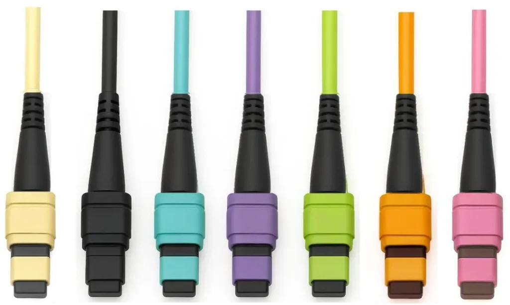
External Connector Housing Colors
| Housing Color | Fiber Type | Application / Notes | Standard |
|---|---|---|---|
|
Gray |
OM1 (62.5/125 μm) |
Legacy systems |
Non-standard |
|
Black |
OM2 (50/125 μm) |
Some vendor-specific builds |
Non-standard |
|
Aqua |
OM3/OM4 (50/125 μm, optimized for 850 nm) |
Short reach, e.g., 40G/100G SR4 |
Standard |
|
Violet |
OM4+/OM5 WBMMF (850–950 nm SWDM) |
Wideband multimode fiber |
Standard |
|
Green |
OS1/OS2 (9/125 μm, APC 8° polish) |
Long-distance, CATV/PON |
Standard |
|
Orange |
OM1/OM2 (62.5/125 μm or 50/125 μm) |
Legacy 100M/1G links |
Standard |
|
Rose Pink |
OM4 (50/125 μm, optimized for 850 nm) |
Some European data centers |
Non-standard |
Frequently Asked Questions
What is the difference between MPO and MTP?
MPO is the generic multi-fiber connector standard, while MTP is an enhanced MPO with improved optical and mechanical performance. They are fully compatible.
What is an MPO-12 connector?
An MPO-12 contains 12 fibers in a single row, commonly used in 40G and 100G applications.
How is MPO polarity managed?
Through three methods (A, B, C), ensuring that transmit and receive fibers align correctly.
Can MPO be connected directly to LC?
Yes, with MPO to LC breakout cables, often called MPO fanouts.
What does an MPO fanout cable do?
It splits a multi-fiber MPO trunk into individual LC or SC connectors for device connections.
Are MPO connectors suitable for AI data centers?
Yes. MPO connectors are widely used in AI data centers because they support high-density, parallel optical transmission required for GPU clusters and large-scale AI workloads. MPO-based architectures simplify cabling for 100G, 400G, and 800G networks while enabling scalable expansion as AI computing demands grow.
In Summary
The MPO connector has become the backbone of modern high-speed optical networks. This is especially true in AI-driven data centers, where scalability and fiber density are no longer optional but essential. From its internal MT ferrule design to the complexity of polarity management, MPO represents a carefully engineered solution balancing optical performance and mechanical robustness. Whether deployed as MPO trunk cables, fanouts, or directly interfaced with transceivers, MPO technology is driving the next generation of data center and telecom infrastructure.
As network demands continue to grow, MPO and MTP connectors will remain essential for achieving cost-effective, scalable, and future-proof optical connectivity.
The End
Well, that’s the end of the breakdown! Hope it was clear enough. 😄
If there’s anything you’re still unsure about, feel free to reach out—we’re always happy to chat more.
And if you’re looking for FTTX or data center–related fiber optic products, we’ve got you covered.
Check out our 【Patch Cord page 】 to explore more!