The LC connector is one of the most widely used interfaces in today’s fiber-optic networks. From patch cords and ODF frames to data-center cabling, its compact 1.25 mm ferrule design makes it ideal for high-density environments.
Although an LC connector looks simple from the outside, the internal structure is a precisely engineered assembly of multiple miniature components—each serving a specific purpose in optical alignment, mechanical stability, and long-term reliability.
This article breaks down the LC connector in detail using engineering drawings and real component photos (LC-01 to LC-08), explaining the function of each part and how different LC structures—0.9 mm, 1.2/2.0 mm, 3.0 mm, dual-fiber, and uniboot—are built.
TABLE OF CONTENTS
Overview:Why LC Connectors Have So Many Variants
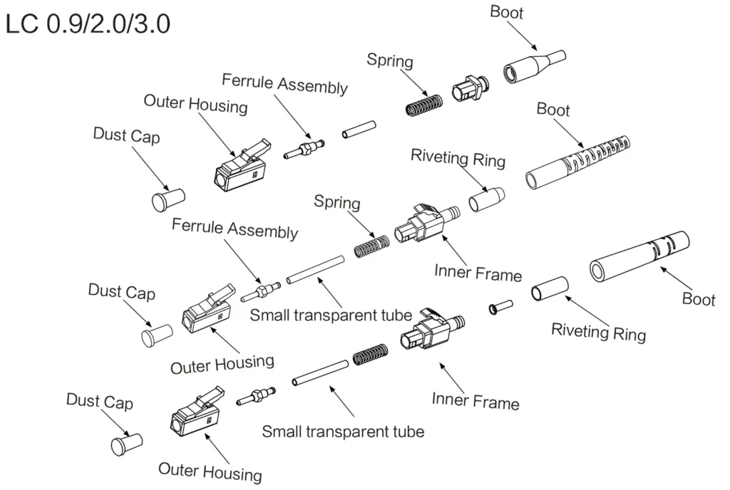
Figure LC-01
LC connectors differ mainly because the fiber cables used with them come in different outer diameters and installation requirements.
For example:
- 0.9 mm is typically used for pigtails and internal equipment wiring.
- 1.2 / 2.0 mm is the most common size for patch cords.
- 3.0 mm is used in environments where stronger mechanical performance is required.
- Duplex LC combines two simplex connectors with a dual clip.
- Uniboot LC routes two fibers in a single-body shell for cleaner, denser cabling.
The general structure can be seen in the engineering overview (Figure LC-01), and all versions are built from the same fundamental idea—just with different reinforcement parts depending on the cable size.
If you would like to explore more fiber optic connector products, please visit our Fiber Optic Connector page. For purchasing inquiries or to request detailed engineering drawings such as 2D/3D views, feel free to contact us anytime.
LC 0.9 mm Structure
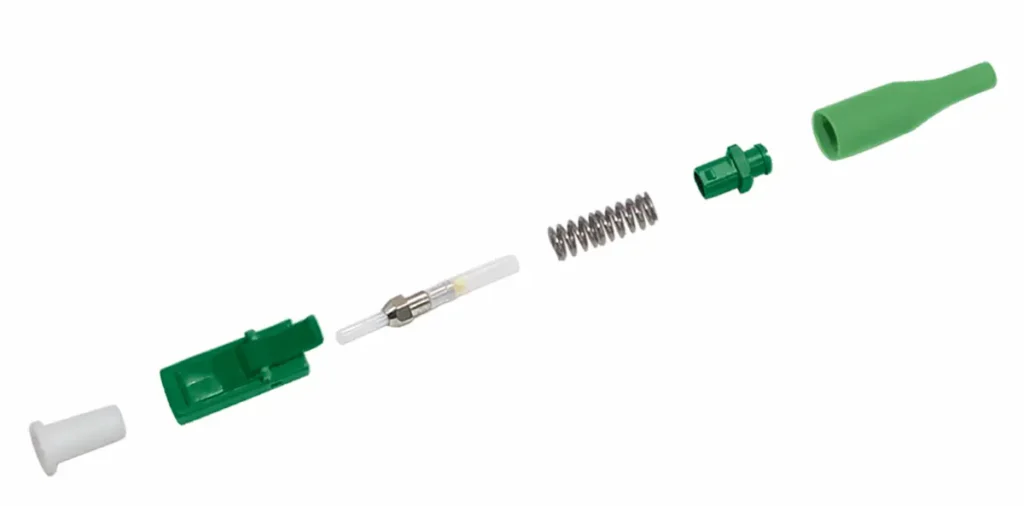
Figure LC-02
The 0.9 mm LC connector is the simplest version.
It does not require a crimp ring or crimp sleeve because the cable itself is extremely light and thin.
The structure includes:
- Outer housing
- Ferrule assembly (ferrule + inner tube)
- Spring
- Rear housing
- 0.9 mm boot
This design is widely used in pigtails and internal equipment wiring, where large tensile strength is unnecessary.
LC 1.2 mm / 2.0 mm Structure
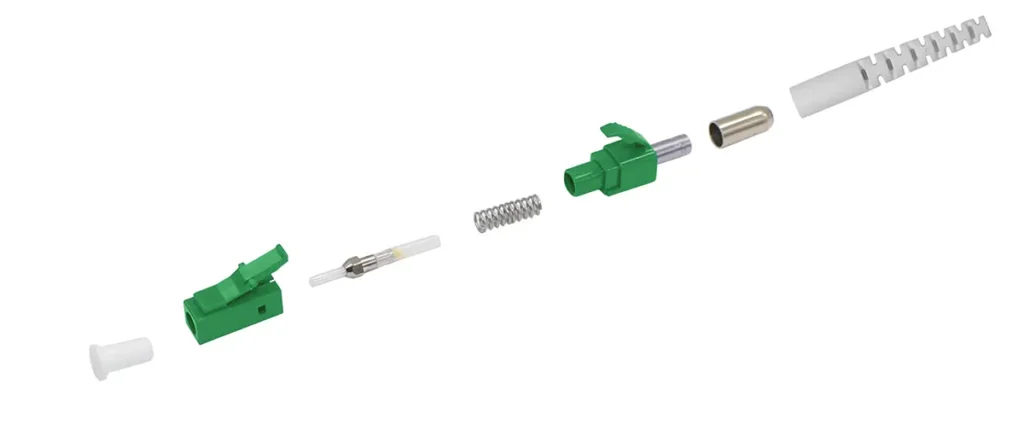
Figure LC-03
This is the most commonly seen LC connector in standard patch cords.
Compared with the 0.9 mm version, it adds an important component:
Crimp Ring — used to secure the Kevlar yarn of the cable.
Inside the connector, the ferrule assembly, inner tube, spring, and rear housing remain the same, but the larger tail requires stronger mechanical fixation.
The 2.0 mm boot is the most frequently used LC tail size in the industry.
LC 3.0 mm Structure
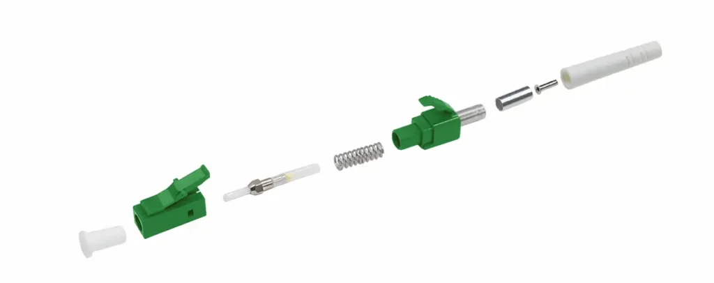
Figure LC-04
The 3.0 mm connector is a strengthened version designed for thicker cables and harsher environments.
Its main difference is an additional part behind the crimp ring:
Crimp Sleeve (Small Tightening Tube) — provides extra holding force for the larger cable diameter.
The 3.0 mm structure is mechanically the strongest among all LC versions, suitable for outdoor jumpers or industrial cables.
Heat-Shrink LC Structure
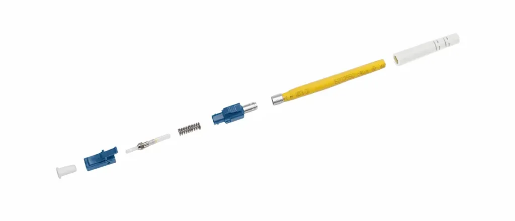
Figure LC-05
In some regions or installation conditions, technicians prefer a heat-shrink fixing method instead of crimping.
This structure uses a heat-shrink tube to hold the fiber and Kevlar securely.
It is commonly used in on-site termination, where crimp tools may not be available.
Duplex LC Connector
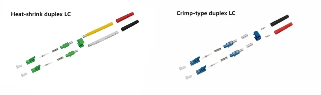
Figure LC-06
A duplex LC connector is essentially two simplex LC connectors paired together using a dual clip.
There are two versions:
- Crimp-type duplex LC
- Heat-shrink duplex LC
The internal structure of each simplex LC remains the same; the dual clip simply links them into a duplex assembly.
This is widely used in duplex transmission applications, such as switches, transceivers, and patch panels.
LC Uniboot Structure

Figure LC-07
The uniboot LC is designed for high-density environments, especially data centers.
Both fibers share one compact outer shell, keeping the cabling cleaner and reducing cable congestion.
The structure typically includes:
- Front and rear housing
- Upper and lower cover
- Heat-shrink tube
- Uniboot tail
- Ferrule assembly and spring
The LC uniboot shown in Figure LC-07 is a polarity-reversible design. By sliding and rotating the upper and lower housing pieces, the polarity can be switched between A-B and B-A without re-terminating the connector.
This design is widely used in data centers because it simplifies polarity management, reduces installation time, and keeps the cabling cleaner and more compact.
LC Boot Size & Color Comparison
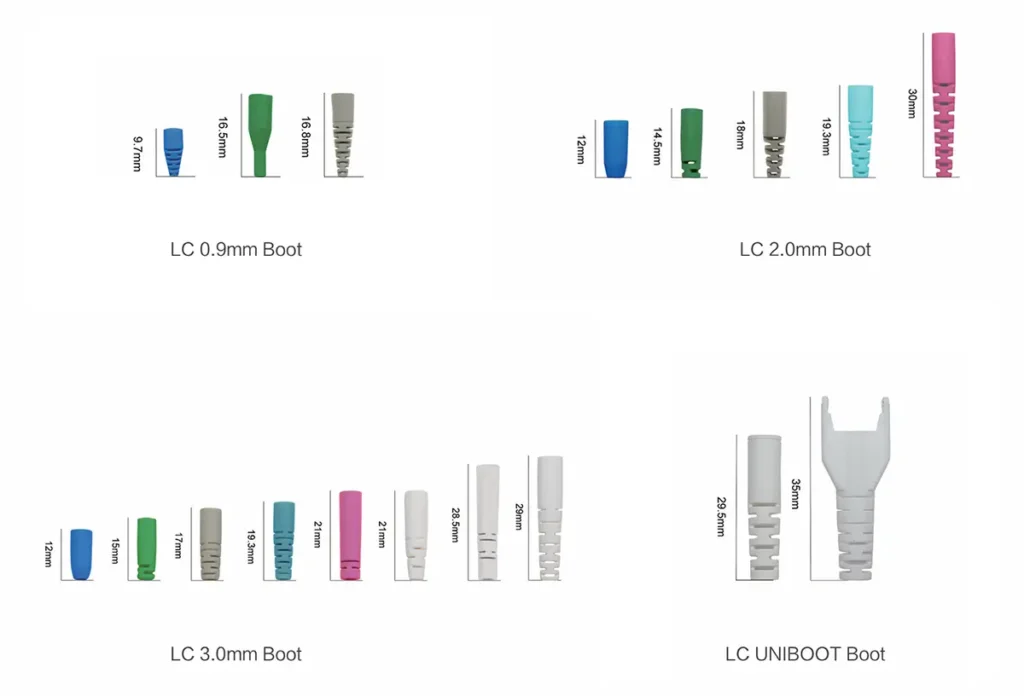
Figure LC-08
LC boots vary by cable size—0.9, 2.0, 3.0, and uniboot.
Colors also follow industry conventions:
- Blue → LC/UPC
- Green → LC/APC
- Aqua / Beige → multimode systems (OM3/OM4)
Why Different LC Structures Use Different Parts
Although all LC connectors share the same optical core, the mechanical structure must adapt to the cable diameter and application:
- Larger cables → stronger rear housing and boot
- More Kevlar → requires a crimp ring
- Thick cables (3.0 mm) → require an additional crimp sleeve
- Duplex and uniboot → completely different outer housing design
- Heat-shrink type → optimized for field termination
- Uniboot → optimized for high-density cabling
Each component exists for a clear mechanical or optical purpose, not simply for “design variety.”
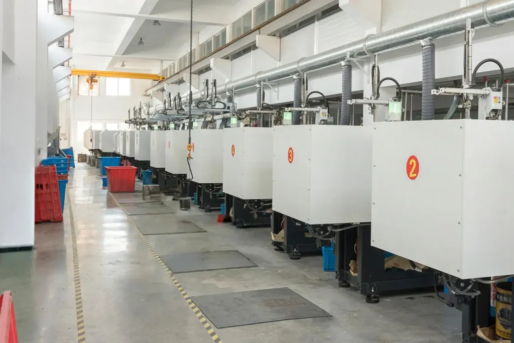
Manufacturing Considerations & Quality Notes
A well-built LC connector depends heavily on precision manufacturing rather than individual components alone.
The ferrule concentricity directly affects insertion loss, while the inner tube must precisely match the ferrule to maintain optical alignment. Spring pressure plays a key role in ensuring stable physical contact, and the accuracy of crimping directly influences long-term tensile strength.
In high-volume production, maintaining consistency across these parameters requires more than component-level control. It depends on engineering evaluation, tooling feasibility, and system-level manufacturing coordination, especially when LC connectors are produced at scale.
Modern factories rely on automated assembly fixtures and validated production processes to achieve this level of consistency. A deeper explanation of how fiber optic components are engineered and manufactured for stable large-scale production can be found in this overview of fiber optic component manufacturing at scale.
YingFeng Communication produces LC connector components and ferrules in large volume and follows GR-326 performance criteria, ensuring compatibility with global telecom requirements and consistent performance across large production batches.
How to Choose the Right LC Connector Structure
A simple guideline:
- For standard patch cords: LC 2.0 mm
- For pigtails: LC 0.9 mm
- For industrial/outdoor: LC 3.0 mm
- For data-center high-density panels: LC uniboot
- For on-site termination: Heat-shrink LC
- For duplex applications: Duplex LC or duplex uniboot
Understanding these structures makes selecting the correct LC version much easier for installers, engineers, and procurement teams.
FAQ — Common Questions About LC Connector
What is the difference between 0.9 mm, 2.0 mm, and 3.0 mm LC connectors?
0.9 mm is mainly used for pigtails and internal device wiring, while 2.0 mm is the most common size for patch cords.
3.0 mm LC connectors are reinforced with a crimp sleeve and are used in applications requiring higher mechanical strength.
What is the function of the crimp ring and crimp sleeve in an LC connector?
The crimp ring secures the Kevlar yarn of 1.2/2.0/3.0 mm cables.
The crimp sleeve (small tightening tube) is used only in 3.0 mm LC connectors to provide additional mechanical reinforcement.
Can LC uniboot connectors reverse polarity?
Yes. Many LC uniboot designs, including the model shown in Figure LC-07, allow polarity reversal without re-terminating the connector. This feature is highly beneficial in data-center environments.
What is the inner tube (inner housing) used for in an LC connector?
The inner tube holds the ferrule in precise alignment and ensures stable axial positioning. It is essential for maintaining low insertion loss and consistent optical performance.
How do I choose the right LC connector structure for my application?
For patch cords, choose LC 2.0 mm; for pigtails, LC 0.9 mm; for industrial or outdoor cables, LC 3.0 mm; for high-density data centers, LC uniboot; and for field termination, choose heat-shrink-type LC connectors.
Conclusion
The LC connector may look small, but inside it is a highly engineered assembly of ferrules, springs, inner tubes, housings, crimp parts, and boots.
By understanding each component and the differences among 0.9 mm, 1.2/2.0 mm, 3.0 mm, duplex, and uniboot versions, users can choose the right structure for their cable type and application needs.
Clear structure knowledge not only helps with installation but also ensures long-term optical performance and system reliability.