In fiber optic communication, light travels through ultra-thin strands of glass — sometimes thinner than a human hair — transmitting data at the speed of light. Yet, even this advanced technology is vulnerable to something as simple as a bend. When a fiber optic cable is bent too sharply, signal loss increases and, in extreme cases, the fiber itself may break.
That’s where the fiber optic bend radius comes in — a crucial parameter that determines how tightly a fiber cable can be curved without causing excessive signal attenuation or physical damage. Understanding this concept helps ensure long-term reliability in everything from data centers to FTTH (Fiber to the Home) networks.
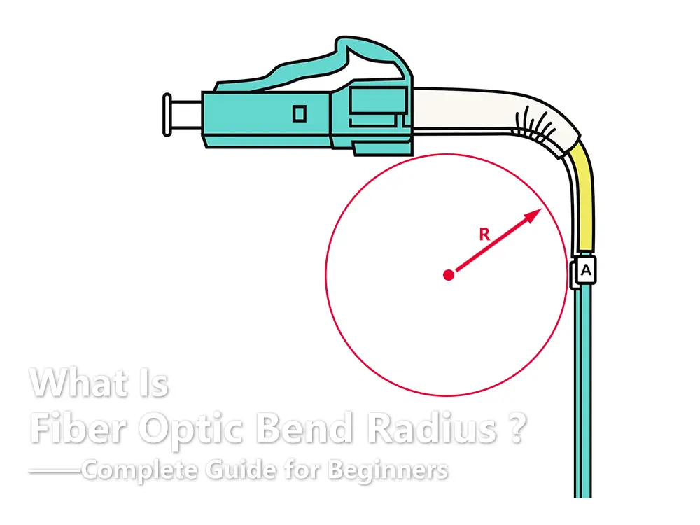
TABLE OF CONTENTS
What Is the Bend Radius of Fiber Optic Cable?
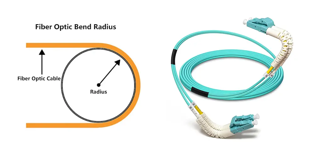
The minimum bend radius is the smallest radius a fiber or cable can be bent into without suffering unacceptable optical loss or damage. Simply put, it tells you how far you can safely bend a fiber optic cable.
Light travels through a fiber’s core by reflecting internally at precise angles. When the cable is bent beyond its design limit, those reflection angles change, and part of the light escapes from the core into the cladding — this is known as bending loss. The tighter the bend, the greater the loss.
Think of it like cars driving along a curved highway:
- On a wide curve, traffic flows smoothly.
- On a sharp curve, some cars may skid off the road — that’s your light escaping.
Minimum Bend Radius: What Does It Really Mean?
You’ll often see fiber specifications list something like:
Min. Bend Radius (Optical Fiber): 10 mm
Min. Bend Radius (Fiber Cable): 20/10D (Dynamic/Static)
But what do these numbers actually mean?
Let’s break it down:
- Optical Fiber refers to the bare glass fiber itself — the thin strand before it’s coated or armored. A bare single-mode fiber typically has a minimum bend radius around 10 mm. This means it should not be bent into a curve tighter than a 10 mm radius, or about the size of a pen cap.
- Fiber Cable, on the other hand, includes multiple fiber strands plus protective coatings, strength members, and jackets. Because of this added structure, the minimum bend radius is usually expressed in terms of the cable diameter (D) and is much larger.
For example:
Static bend radius (10D) applies when the cable is installed and left in place — e.g., coiled inside a panel.
Dynamic bend radius (20D) applies during installation, when the cable is being pulled or moved.
So if your cable has a 3 mm diameter, the minimum static bend radius would be 30 mm, and the minimum dynamic bend radius would be 60 mm.
👉 In other words, when you see a manufacturer’s specification labeled “Minimum Bend Radius,” it almost always refers to the fiber cable, not the bare optical fiber.
How Much Can You Bend a Fiber Patch Cord?
For practical applications like fiber optic patch cords, most standard cables have a minimum bend radius of about 30 mm (3 cm). That’s roughly the size of a large coin — tighter than that, and you risk signal degradation or even permanent fiber damage.
However, high-end patch cords from premium manufacturers such as Corning, CommScope, and OFS use bend-insensitive fibers (BIF). These special designs can tolerate bends as tight as 10–15 mm, making them ideal for cramped spaces, indoor wiring, and data center environments.
The trade-off, however, is cost — such advanced cables can be two to three times more expensive than standard products. While not always necessary for every installation, they’re an excellent choice for performance-critical networks where space and signal quality are both top priorities.
Why Bend Radius Matters
Even small bends can have significant effects on optical performance. When the fiber is curved beyond its minimum radius, part of the light signal escapes, leading to higher attenuation (signal loss). Over time, repeated or excessive bending can also cause micro-cracks in the fiber, reducing its lifespan and reliability.
In short, maintaining the correct bend radius ensures:
- Stable signal transmission – minimizing power loss and reflection.
- Longer cable life – preventing stress and fatigue in the glass core.
- Reduced maintenance costs – fewer failures, fewer replacements.
Many network issues that appear as “slow speed” or “connection drops” are actually the result of fiber cables being bent too tightly — often behind wall plates, inside racks, or during installation.
Factors That Affect Fiber Optic Bend Radius
Not all fiber optic cables are created equal — and neither are their bend radii. Several factors determine how tightly a fiber can bend before it starts losing signal or sustaining damage. Understanding these factors helps engineers choose the right cable for each environment.
1. Fiber Type
Single-mode fibers (SMF) generally have smaller cores and are more sensitive to bending compared to multimode fibers (MMF). A sharp bend in an SMF can cause significant power leakage because light travels in a very narrow path. In contrast, MMF has a wider core and can tolerate slightly tighter bends — but both still require careful handling.
2. Cable Construction
The overall design of a fiber optic cable plays a major role in its bend performance.
- Loose tube cables (common for outdoor use) have fibers inside gel-filled tubes that offer flexibility but require a larger bend radius.
- Tight-buffered cables (used indoors) allow for smaller bend radii and are easier to handle in confined spaces.
- Armored cables with steel tape or corrugated armor have higher rigidity and larger bend radii.
Each layer — jacket, strength member, buffer — adds stiffness, which means the bend radius for a fully assembled cable will always be larger than for a bare fiber.
3. Temperature and Environment
Temperature fluctuations can make materials expand or contract, altering flexibility. Extremely cold environments make cables more brittle, increasing the risk of microbending. In high-temperature conditions, materials soften, which may temporarily allow tighter bends but also increase long-term stress.
4. Installation Practices
The way the cable is installed is often the biggest variable.
- Pulling the cable around tight corners,
- Overstuffing conduits,
- Using improper reels or cable ties — all can exceed the bend radius and introduce permanent microbending loss.
Following manufacturer guidelines and using fiber-friendly routing accessories (like wide-radius raceways and bend limiters) are key to maintaining signal integrity.
Types of Bending Loss
Bending losses in optical fibers are generally classified into two main types: macrobending and microbending.
Macrobending
Macrobending occurs when the fiber is bent in a large, visible curve beyond its minimum bend radius. This type of loss is relatively easy to identify because the affected section often looks physically bent. The light escaping from the core appears as a measurable drop in power at the receiver.
Macrobending can occur during:
- Routing cables around sharp edges,
- Coiling patch cords too tightly,
- Forcing fibers into narrow conduits.
Microbending
Microbending happens on a much smaller scale — often microscopic distortions in the fiber geometry caused by uneven pressure, improper jacket compression, or rough handling. Even small deformations can scatter light and increase attenuation.
Microbending losses are harder to detect visually. They may not break the cable, but they degrade signal quality over time and can cause intermittent network errors. Testing tools like OTDR (Optical Time Domain Reflectometer) are commonly used to identify such hidden losses.
Testing and Measurement of Bend Loss
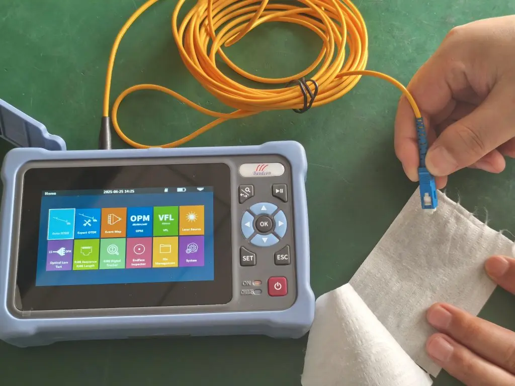
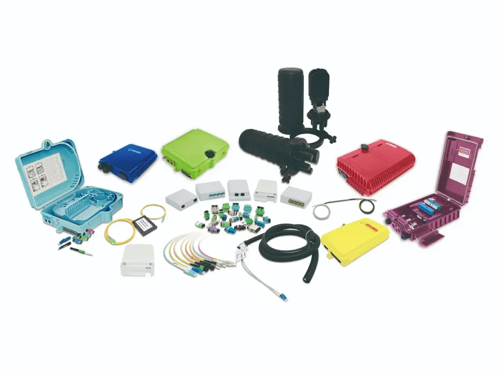
Image source: Baudcom
Testing fiber optic bend performance ensures the system meets design standards and link budget requirements. The most common methods include:
- Power Meter and Light Source – Measure insertion loss before and after bending the cable. Any increase in loss indicates bending effects.
- OTDR Testing – Sends a pulse of light down the fiber and measures reflections and backscatter. Sharp bends or damaged areas appear as spikes on the OTDR trace.
- Visual Fault Locator (VFL) – A red laser used to visually identify macrobends and breaks in short fiber runs.
When testing, technicians often follow a “bend test” procedure — wrapping the fiber around a mandrel of specific diameter to ensure compliance with the rated bend radius.
Best Practices to Prevent Bending Loss
Proper installation and handling can eliminate most bending-related problems. Here are a few best practices followed by experienced fiber engineers:
- Respect the minimum bend radius listed by the manufacturer — never exceed it, even temporarily.
- Avoid tight 90° turns when routing cables. Use gentle curves or fiber guides.
- Do not over-tighten cable ties or clamps. Use Velcro straps instead of plastic zip ties.
- Keep spare loops wide when coiling extra cable — never force it into a tight bundle.
- Inspect connectors for stress or kinks during installation.
- Use bend-insensitive fiber for installations in confined spaces or with multiple corners.
Even small improvements in cable management can result in significant gains in long-term network reliability.
The Role of Bend-Insensitive Fiber
Modern fiber networks often rely on bend-insensitive fibers (BIF) — especially in environments like apartment buildings, offices, or data centers where space is limited.
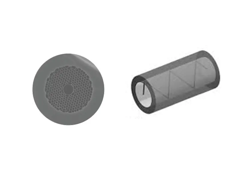
Bend-insensitive fibers use a special optical design that includes a modified cladding layer. This structure helps confine light within the core, even when the fiber is bent sharply. As a result, signal loss remains minimal, and installation becomes easier and safer.
These fibers are widely used in FTTH (Fiber to the Home), FTTB (Fiber to the Building), and data center interconnects where cables must navigate small trays and racks.
At YingFeng Communication, we provide a complete range of bend-insensitive optical fibers, patch cords, and pigtails, helping our customers deploy high-performance networks even in the most space-constrained environments. Our factory’s precision manufacturing ensures low insertion loss, high return loss, and superior durability across all fiber products.
FAQ: Fiber Optic Bend Radius
What happens if I bend a fiber optic cable too tightly?
Bending a cable beyond its minimum bend radius causes light to leak from the core, increasing attenuation and potentially damaging the fiber.
What is the typical minimum bend radius for standard patch cords?
Most standard fiber patch cords have a minimum bend radius of around 30 mm, though bend-insensitive models can go as low as 10–15 mm.
Why are there “static” and “dynamic” bend radius specifications?
Static bend radius applies when the cable is stationary after installation. Dynamic bend radius applies during installation or movement — when the cable is being pulled, twisted, or coiled.
Can environmental conditions affect bend radius performance?
Yes. Extreme cold makes cables stiffer and more prone to cracking, while heat and humidity can alter flexibility. Always follow manufacturer guidelines for the specific environment.
Do all fiber types have the same bend radius?
No. Single-mode fibers generally have larger bend radius requirements than multimode fibers. Bend-insensitive versions are specifically engineered to handle tighter curves.
In Summary
The fiber optic bend radius is one of the most important — yet often underestimated — factors in network performance. Whether in telecom backbones, FTTH deployments, or compact data centers, respecting bend radius limits ensures reliable, long-lasting connections.
Remember:
- Too tight a bend leads to higher loss, reflection, and even permanent fiber damage.
- Following installation best practices and using bend-insensitive fiber can significantly reduce problems.
At YingFeng Communication, we understand the importance of mechanical precision and optical performance. That’s why our fiber optic patch cords, bend-insensitive cables, adapters, and connectors are all engineered to maintain low signal loss and high reliability — even under challenging routing conditions. From production to testing, every detail ensures that your network stays strong, stable, and future-ready.