Written by Bo Ying, Yingfeng Senior Technical Specialist.
Edited and curated by Quinn Zhang, Fiber Optic Manufacturing Content Specialist
Key Takeaways
- Large-scale manufacturing of custom fiber plastic components depends on engineering evaluation, not just production capacity.
- OEM fiber optic components require mold feasibility and manufacturability validation before tooling.
- Trial molding combined with international standard compliance testing ensures stable quality before mass production.
System-level engineering significantly reduces risk in complex fiber optic OEM projects such as FTTX and data centers.
TABLE OF CONTENTS
Introduction
In the fiber optic industry, many components appear simple in form. However, once production moves beyond prototypes and into large-scale OEM manufacturing, the real challenges begin to surface. Manufacturing custom fiber plastic components at scale is not defined by equipment quantity or labor capacity alone. It is a structured, engineering-driven process involving design evaluation, mold feasibility, trial molding, quality validation, and coordinated system-level control.
This article explains how OEM fiber optic plastic components are developed and manufactured in a high-volume factory environment—from initial engineering discussions to long-term stable mass production.
Engineering Evaluation for Custom & OEM Fiber Plastic Components
Every custom or OEM project begins with a customer requirement, but not every requirement is immediately suitable for manufacturing. In practice, customer requests usually fall into two categories:
- Customization based on existing fiber plastic component designs.
- Completely new OEM designs requiring full engineering evaluation.
Before any tooling or production activity begins, our engineers evaluate critical factors including the application environment (FTTX, data center, etc.), core functional and mechanical requirements, dimension tolerances, and material selection. At this stage, the key question is not whether a design works in theory, but whether it can be manufactured consistently, reliably, and repeatedly at scale. Once the theoretical design is validated, the project moves into the physical tooling phase where the focus shifts to mold precision.
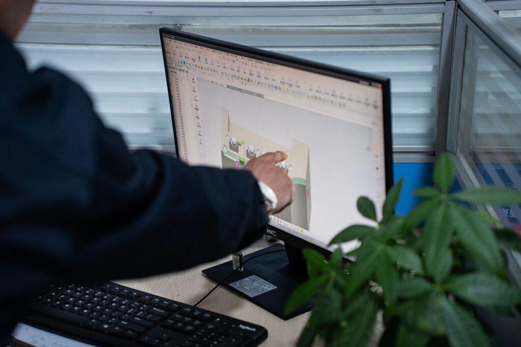
Mold Design & Manufacturability Validation

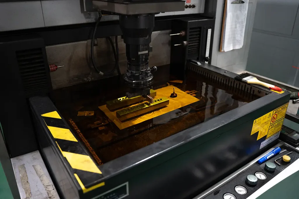
Mold design is not a simple conversion of drawings into steel.
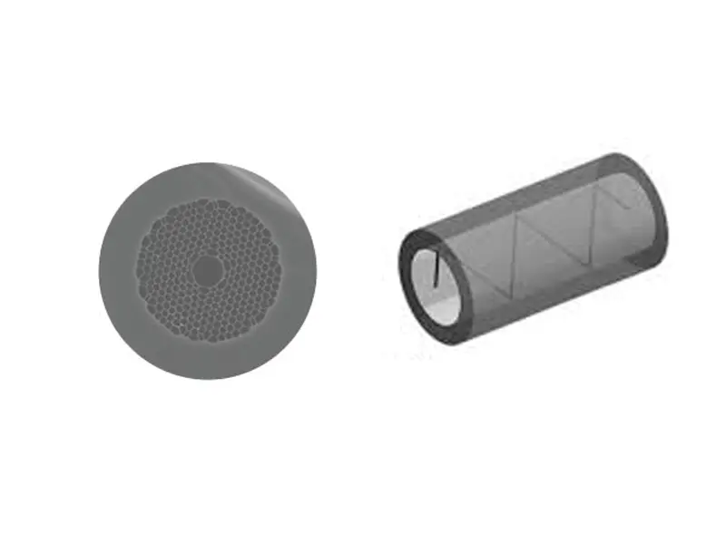
In fiber optic plastic components, many designs appear feasible in theory but encounter limitations during actual injection molding. A common example is extremely small structural features. While a dimension such as 0.1–0.2 mm may look acceptable on paper, molten plastic may not properly fill such cavities during molding. Increasing injection pressure to compensate can introduce new risks, such as material stress or structural failure in other areas.
Fiber optic plastic components often include small structural features, thin walls, or tight tolerances that can introduce instability during actual injection molding.
During the mold feasibility review, engineers focus on plastic flow behavior, structural strength, and the risk of deformation or internal stress. Through close collaboration between product and mold engineers, designs are adjusted to balance functional performance with long-term production stability. The objective is to ensure stable output under real-world production conditions rather than preserving the original design at all costs.
Trial Molding, Quality Control & International Standard Compliance
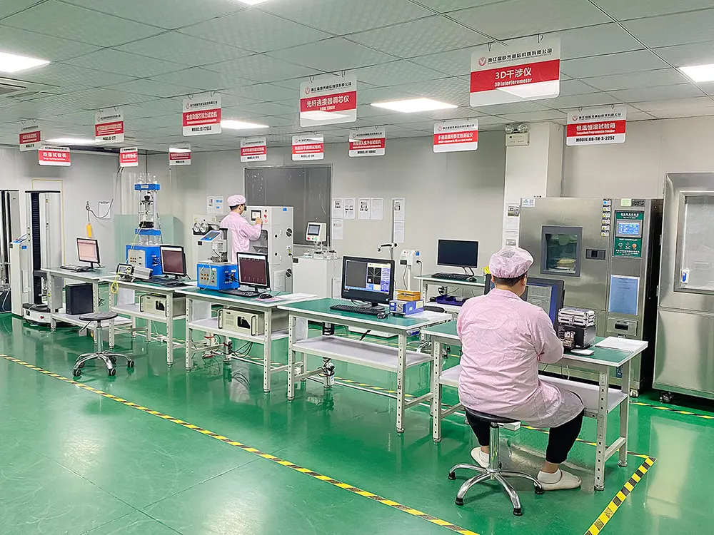
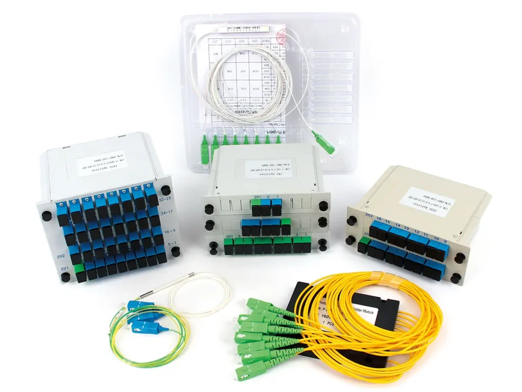
After mold completion, production does not immediately move to mass output. Instead, trial molding and small-batch validation are conducted to verify production behavior and quality consistency. During this stage, we monitor surface appearance, dimensional accuracy, and color consistency.
Beyond physical measurements, we ensure performance through rigorous testing against application-specific international standards:
- Fiber Optic Connectors: Compliance testing based on Telcordia GR-326-CORE, focusing on insertion loss, return loss stability, and mechanical durability.
- Terminal Boxes & Enclosures: Testing according to IEC standards for mechanical strength and environmental resistance.
- Customer-Specific OEM Components: Testing based on EIA/TIA standards or customized validation plans.
Only products that pass both trial molding and these strict compliance tests proceed to the final stage of mass production.
From Prototype to Stable OEM Mass Production
Development timelines vary based on complexity: modified designs may enter production within one month, while fully custom OEM components may require up to one year. Stable mass production is achieved only after materials, molds, processes, and assembly methods have been fully validated. This foundational stability is what allows for scaling; without it, increasing volume only amplifies existing quality risks.
System-Level Engineering for Fiber Optic Projects
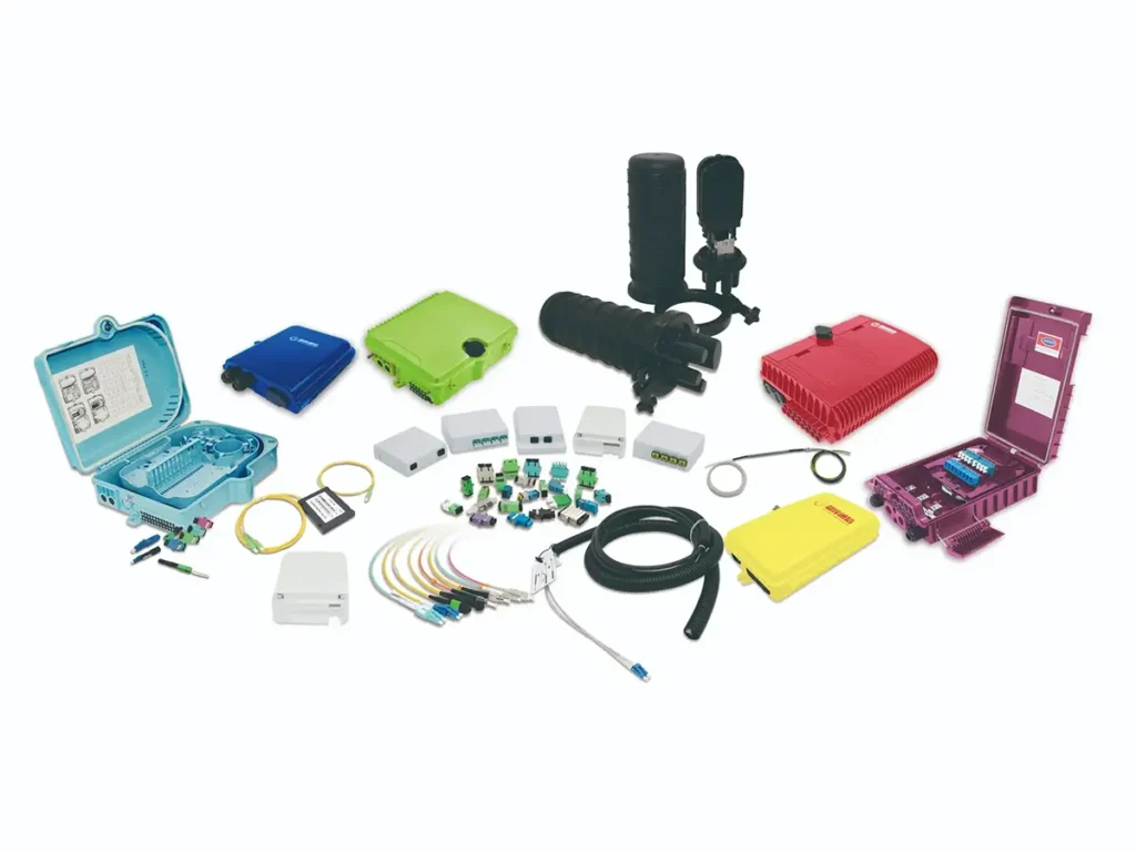
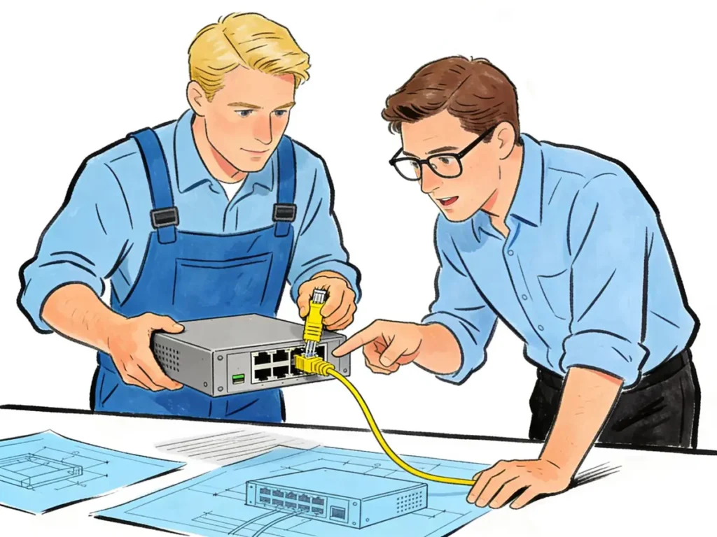
In real-world fiber optic projects, components rarely function independently. Plastic housings, adapters, connectors, patch panels, cable routing structures, and sheet metal parts all interact within a single system. If these elements are designed or sourced separately without unified engineering coordination, hidden risks often appear during assembly or deployment.
For this reason, system-level engineering capability is critical in large-scale fiber optic manufacturing.
From the earliest design stage, components must be evaluated not only as individual parts, but as elements within a complete optical system. Structural compatibility, bending radius control, fastening mechanisms, assembly tolerances, and long-term reliability all need to be considered together. When these factors are planned under a unified engineering framework, many downstream issues can be avoided before production begins.
Unified engineering control offers several advantages:
- Reduced assembly conflicts between different components
- Better control of optical parameters and mechanical tolerances
- Faster iteration when design adjustments are required
- Lower risk in project-based and large-volume deployments
In complex applications such as FTTX networks and data centers, this level of coordination becomes increasingly important. System-level planning allows manufacturers to respond efficiently to design changes while maintaining production stability and delivery reliability.
Practical OEM & Custom Project Collaboration Examples:
The advantages of unified engineering and system-level planning are most visible in real project collaboration.
In several FTTX deployments with international partners, system-level coordination played a key role during early product development. Instead of evaluating components individually, engineering teams worked together to define the overall structure and interface logic. In one case, on-site discussions between customer engineers and factory engineers allowed the core product framework to be confirmed within a single working session. This significantly shortened the development cycle and reduced later design revisions during deployment.
Similarly, in data center fiber optic projects with European partners, system-level planning helped align plastic components, internal routing structures, and installation requirements from the start. By treating the project as a complete system rather than a collection of parts, multiple new products were developed with stable performance and smooth integration into existing infrastructure.
These types of collaboration demonstrate how unified engineering control can improve efficiency, reduce risk, and support long-term project success—especially in applications where reliability and scalability are critical.
Common Pitfalls in Fiber Optic Component Manufacturing
The Gap Between Theory and Production
A design that appears feasible in theory may behave very differently during molding or assembly. Without proper engineering evaluation, these gaps often lead to repeated modifications, delays, or unstable quality.
Ignoring Mass Production Requirements
Molds should always be designed with mass production in mind. If a structure cannot be produced consistently at scale, engineering revision is required before tooling, not after.
Multi-Supplier Project Risks
Projects involving multiple suppliers often face hidden challenges:
- Designers from different industries may lack shared technical understanding
- Parameters between components may not align
- Assembly compatibility issues may only appear late in the process
- Delays from a single supplier can affect the entire project
- Communication and logistics costs increase significantly
These risks grow as project complexity increases.
Frequently Asked Questions (FAQ)
Can fiber plastic components be customized for OEM projects?
Yes. Most components can be customized in structure, material, and function after engineering evaluation.
What quality standards are used for testing?
Testing follows Telcordia GR-326-CORE, IEC standards, EIA/TIA standards, or customer-specific requirements.
How long does OEM product development usually take?
Timelines range from one month for modified designs to one year for fully custom components.
Why is trial molding important?
It verifies real production behavior and prevents large-scale quality issues.
Can testing protocols be customized?
Yes. OEM projects often use customized validation plans based on specific application needs.
Conclusion
Manufacturing fiber optic components at scale is a combination of engineering judgment, production experience, and process control. Equipment and capacity alone are not enough.
What ultimately determines success is the ability to evaluate designs realistically, control critical manufacturing stages, coordinate multiple product categories, and ensure long-term production stability. For customers seeking reliable supply and consistent quality, these capabilities are often more important than individual component specifications.