Written by: Ying Bo, Fiber Optic Enclosure Engineer at YingFeng Communication
Edited and organized by: Quinn Zhang
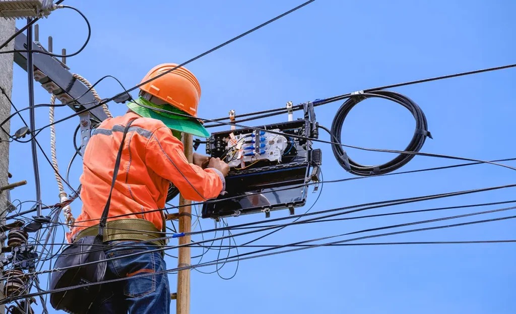
In real fiber optic networks, cables are rarely installed as one continuous, uninterrupted length. Along transmission routes—whether in access networks, metro networks, or backbone infrastructure—fiber cables must be joined, branched, repaired, or reserved for future expansion.
But every one of these connection points introduces potential risk.
This is exactly why fiber optic splice closures play such a critical role in modern fiber networks. They are not optional accessories, nor simple protective boxes. They are engineered systems designed to protect fiber splices from mechanical stress, environmental exposure, and long-term performance degradation.
This guide is written to provide a complete and engineering-oriented understanding of fiber optic splice closures—from basic concepts and classifications to structural logic and practical deployment considerations. Rather than focusing on a single product or brand, the article explains: how splice closures work and how they should be understood in real projects.
TABLE OF CONTENTS
Why Fiber Optic Splice Closures Matter in Real Networks
Fiber splicing is unavoidable in real-world deployments. Cables must be joined due to route length limitations, branching requirements, repairs after damage, or network upgrades.
However, once fibers are spliced, the joint itself becomes one of the most vulnerable points in the entire network.
Without proper protection, fiber splices face multiple long-term risks:
- Mechanical stressfrom pulling, vibration, compression, or accidental impact
- Environmental exposuresuch as moisture, dust, temperature cycling, UV radiation, or chemicals
- Optical instability, where micro-bending or fiber movement gradually increases signal loss
A fiber optic splice closure creates a controlled protective environment for these spliced fibers. Its role is not only to enclose the splice, but to ensure that optical performance remains stable throughout years of operation.
In FTTX and outdoor access networks especially, the reliability of splice closures often determines whether a network operates maintenance-free or becomes a recurring repair problem. From an engineering standpoint, splice closures are a fundamental part of network reliability—not an afterthought.
Real-World Deployment Example: How Many Splice Closures Are Used in Practice?
Fiber splice closures are not used occasionally — they are deployed extensively across every fiber network.
The exact quantity depends on population density, network topology, and regional infrastructure planning. Below is a simplified example based on a 10 km coverage area serving approximately 10,000 FTTH users.
Estimated Splice Closure Usage by Region
| Region | Typical Deployment Environment | Estimated Quantity |
|---|---|---|
|
United States |
Suburban Deployment |
35 – 60 closures |
|
Europe (Old Town Areas) |
Dense, Structured Layout |
24 – 36 closures |
|
Europe (Suburban / Mixed) |
Medium Density |
32 – 48 closures |
|
China |
Urban / Mixed Density |
24 – 36 closures |
|
Southeast Asia |
Urban / Mixed |
28 – 100 closures |
Note: These numbers represent planning examples, not fixed standards.
Why Does the Quantity Differ?
Even with the same number of users (10,000 FTTH subscribers), splice closure quantity varies due to:
- Network branching strategy
- Cable routing structure
- Building distribution style
- Population density
In general:
- Lower population density → more branching → more splice closures required
- Higher population density within the same planning area (per km²) → more distribution points → increased splice closure usage
In other words, fiber splice closures are fundamental infrastructure components. Their deployment density directly reflects network design logic.
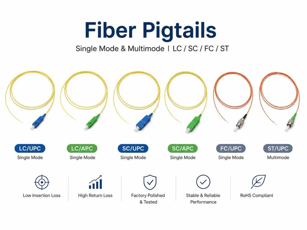
What Is a Fiber Optic Splice Closure
A fiber optic splice closure is a protective enclosure designed to house and protect fiber optic splices and, in some cases, passive optical components. It provides mechanical protection, environmental sealing, and internal fiber management for spliced optical fibers.
It is important to distinguish splice closures from other fiber enclosures:
- Fiber splice closure
Primarily used along transmission routes to protect spliced fibers. - Fiber distribution box or termination box
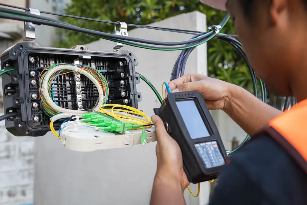
Typically installed at access points where fibers are terminated, distributed, or connected to patch cords.
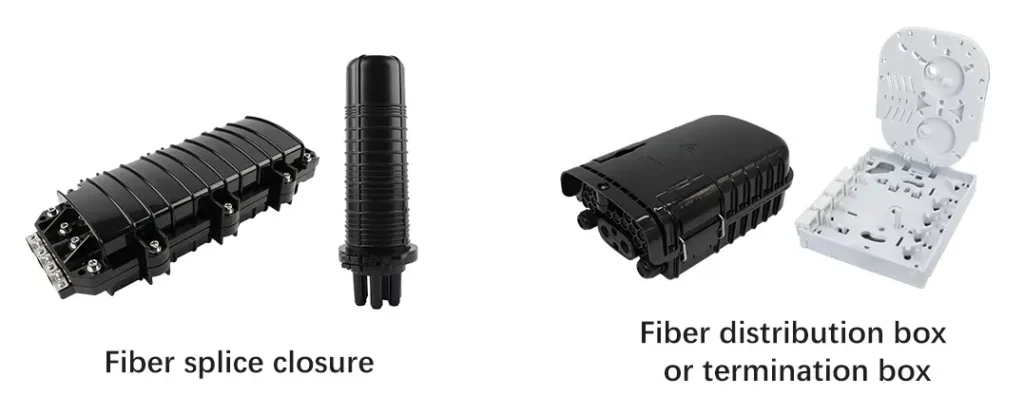
In network topology, a splice closure usually sits between cable segments, rather than at user-facing endpoints. Its primary responsibility is long-term protection and stability, not convenience of patching.
How a Fiber Optic Splice Closure Works
From a functional perspective, a fiber optic splice closure must address three core requirements at the same time.
Mechanical Protection
The closure shields delicate fiber splices from external forces such as pulling, bending, vibration, and impact. Proper internal fixation ensures that mechanical stress applied to the cable sheath is not transferred directly to the fiber joints.
Optical Performance Stability
Optical fibers are extremely sensitive to micro-bending and movement. A well-designed splice closure maintains controlled fiber routing and minimum bending radius, helping preserve insertion loss and signal quality over time.
Cable Strain Management
In real installations, fiber cables experience long-term tension caused by installation methods, temperature changes, wind load (in aerial routes), or ground movement.
Splice closures incorporate cable fixation and strain relief structures so that these forces are absorbed by the enclosure body rather than the fiber splices themselves.
A useful way to understand this is to view a splice closure as a protective house for fiber joints. The enclosure itself forms the building structure, shielding fibers from weather and external damage. Inside, splice trays function like organized rooms, keeping fibers fixed, separated, and properly routed. Cable fixation and strain relief act as the foundation, ensuring that forces applied outside do not disturb the delicate splices inside.
Without this “house,” spliced fibers would be directly exposed to environmental and mechanical risks, leading to unstable performance and frequent maintenance.
Entry & Exit Configuration Explained
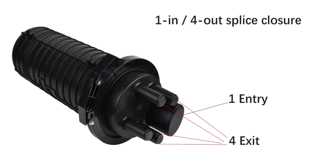
One of the most common specifications associated with fiber optic splice closures is entry and exit configuration, often described as “X-in / Y-out”.
In simple terms:
- Entryrefers to the number of fiber optic cables entering the closure
- Exitrefers to the number of fiber optic cables leaving the closure
For example, a 2-in / 2-out splice closure allows two cables to enter and two cables to exit, typically used in straight-through network segments. A 2-in / 3-out configuration is often used in branching scenarios.
For beginners, this can be understood with a simple analogy.
Think of a splice closure as a house, and fiber optic cables as roads connected to it. The entry and exit ports define how many roads can enter or leave the house. They do not describe how many people live inside, nor how the rooms are arranged.
Similarly, entry and exit numbers only indicate cable routing capability—they do not represent fiber count, splice quantity, or internal fiber organization.
Two common misunderstandings should be avoided:
- Entry/exit count does not equal fiber core count
- Entry/exit count does not directly indicate splice capacity
A single cable may contain dozens or even hundreds of fibers. Entry and exit configuration reflects external cable management, not internal fiber density.
Main Types of Fiber Optic Splice Closures
Fiber optic splice closures can be classified in several practical ways. These classifications describe deployment logic, not product quality.
Classification by Structural Design
| Type | Description | Typical Characteristics |
|---|---|---|
|
Horizontal (Inline) |
Two-part housing with cable entries on both ends |
Compact, suitable for duct or aerial routes |
|
Vertical (Dome) |
Cylindrical or dome-shaped structure |
Flexible cable routing, commonly used outdoors |
Structural form alone does not determine performance. Sealing design, internal layout, and cable fixation are equally important.
Classification by Network Topology
| Type | Application |
|---|---|
|
Straight-through splice closure |
Connects cables along the same transmission route |
|
Branching splice closure |
Allows fibers to branch toward different directions |
Branching closures are widely used in access networks where future drop connections are expected.
Classification by Installation Method
- Aerial installation
- Duct installation
- Pole-mounted installation
- Wall-mounted installation
Each installation method places different requirements on mechanical strength, sealing performance, and strain relief.
Classification by Fiber Capacity
Typical nominal capacities include 12, 24, 48, 96, 144, and 288 fibers. In practice, splice closures are rarely filled to maximum capacity at initial installation. Capacity planning usually includes allowance for future expansion.
A high-capacity splice closure can support low fiber counts, but a low-capacity closure cannot be expanded once fully occupied.
Overall Structure of Fiber Optic Splice Closures
While fiber optic splice closures vary in form and capacity, their overall structural logic is consistent. The following outlines the typical structural components of the two most common designs. These sections are best understood together with structural diagrams.
Vertical (Dome-Type) Splice Closure Structure
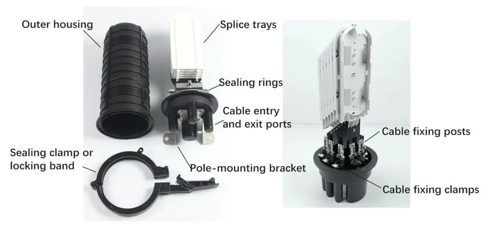
A typical vertical splice closure consists of: Outer housing, Sealing clamp or locking band, Splice trays, Sealing rings, Cable entry and exit ports, Pole-mounting bracket (if applicable), Cable fixing posts, Cable fixing clamps.
This design allows flexible cable routing and is commonly used in outdoor, aerial, and underground environments.
Horizontal (Inline-Type) Splice Closure Structure
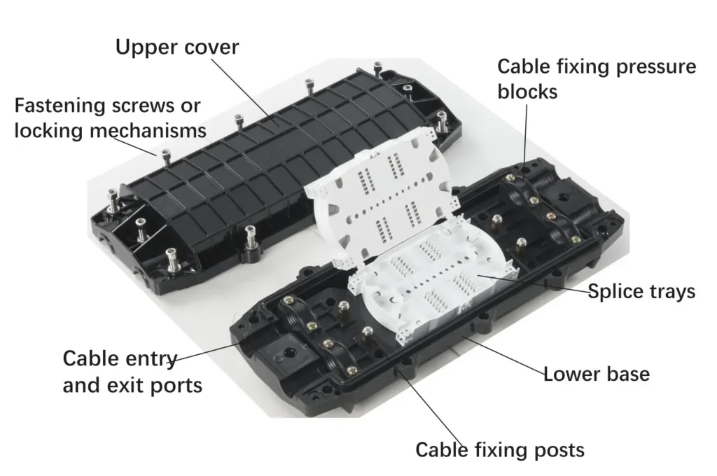
A typical horizontal splice closure includes: Upper cover, Lower base, Fastening screws or locking mechanisms, Cable entry and exit ports, Cable fixing pressure blocks, Splice trays, Cable fixing posts
Horizontal closures are often favored for duct installations and straight-through network segments due to their compact and symmetrical layout.
Internal Structure and Fiber Management System
Inside a splice closure, fiber organization is not a matter of convenience—it is a matter of optical stability and maintainability.
A well-designed fiber management system ensures that fibers remain protected not only at installation, but also during future re-entry and maintenance operations.
Splice Trays
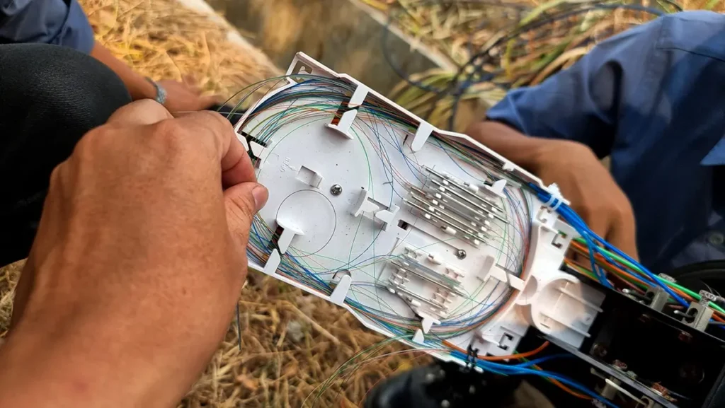
Splice trays are the core working units inside a fiber optic splice closure. Their main purposes include:
- Securing fusion splices
- Maintaining minimum bending radius
- Preventing fiber crossing, pinching, or displacement
From field experience, many long-term failures are not caused by poor splicing quality, but by fiber movement or micro-bending introduced by inadequate tray design.
Key tray design considerations include:
- Stackable or hinged tray structures
- Clear fiber routing paths between trays
- Support for single fiber and ribbon fiber splicing
- Sufficient slack storage for re-entry operations
Closures designed for access networks often prioritize flexibility and ease of tray access, while backbone closures emphasize density and long-term stability.
Fiber Routing and Bend Radius Control
Optical fibers are highly sensitive to bending stress. Even when insertion loss is acceptable at installation, poor routing can lead to gradual degradation over time.
A reliable splice closure design ensures:
- Smooth transitions from cable entry to splice tray
- No sharp edges or compression points
- Consistent bending radius throughout the enclosure
In practice, a stable internal routing design is often more important than nominal fiber capacity.
Cable Fixation and Strain Relief
Cable fixation is one of the most critical—and most overlooked—elements of splice closure design.
In real deployments, cables may be subjected to:
- Long-term tensile forces
- Wind-induced vibration (aerial installations)
- Ground movement or thermal expansion
Effective strain relief ensures that these forces are absorbed by the enclosure structure rather than transferred to fiber splices.
Closures with weak cable fixation often appear stable initially, but develop faults months or years later.
Materials and UV-Resistant Housing
Material selection directly affects mechanical strength, aging behavior, and environmental resistance.
It is worth noting that most leading manufacturers do not publicly disclose detailed polymer formulations, making it difficult to define a single “industry standard” material.
Common Material Characteristics
Rather than focusing on exact material names, engineers typically evaluate splice closure housings based on performance characteristics such as:
- Impact resistance
- Long-term aging behavior
- Resistance to UV exposure
- Stability under temperature cycling
Many outdoor splice closures feature UV-resistant housing designs intended to minimize degradation during long-term sun exposure. In outdoor telecom environments, material stability over time is often more critical than initial mechanical strength.
Sealing Design and Re-Enterable Sealing
Among all design elements, sealing performance has the greatest impact on long-term reliability.
Fiber optic splice closures must maintain sealing integrity while also allowing for future maintenance. This requirement leads to the widespread use of re-enterable sealing designs.
Common Sealing Approaches
Typical sealing methods include:
- Mechanical sealing using gaskets or O-rings
- Heat-shrink sealing systems
- Gel-based sealing solutions
Mechanical sealing is widely adopted due to its ease of installation and re-entry. Heat-shrink solutions provide strong sealing but are less convenient for repeated access. Gel sealing offers flexibility but requires careful material compatibility.
From an engineering perspective, sealing reliability after multiple open–close cycles is just as important as initial sealing performance.
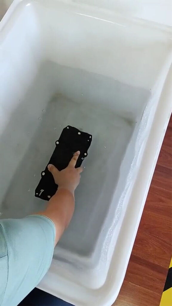
Testing and Standards for Fiber Optic Splice Closures
One area often overlooked in online guides is how splice closures are actually tested and validated. In real engineering practice, performance claims must be supported by standardized testing.
Fiber optic splice closures are typically evaluated through a combination of mechanical performance tests and environmental performance tests.

Why Testing Matters
A splice closure may appear robust at installation, but long-term reliability depends on its ability to withstand:
- Mechanical stress
- Environmental exposure
- Repeated handling during maintenance
Testing provides objective verification that a closure can perform under these conditions.
Mechanical Performance Tests
Mechanical tests evaluate the structural integrity of the closure and its ability to protect fiber splices under physical stress. Typical test items include:
- Tensile (axial pull) testing
- Compression resistance
- Impact resistance
- Bending and torsion resistance
These tests assess whether mechanical forces applied to the cable or enclosure are properly isolated from the fiber splices inside.
Environmental Performance Tests
Environmental tests simulate long-term exposure conditions commonly encountered in outdoor deployments, such as:
- Temperature cycling
- High humidity and water immersion
- Dust and particle ingress
- UV exposure
Rather than testing isolated components, these evaluations examine the combined performance of housing material, sealing system, and structural design.
Applicable Standards and Test References
Fiber optic splice closure testing is commonly referenced against recognized international and industry standards, including:
- ITU-T L.13– Requirements for optical fiber cable joints
- IEC 61300-2– Fiber optic interconnecting device test methods
- GR-771-CORE– Generic requirements for fiber optic splice closures
These standards define test methods, conditions, and acceptance criteria. While not all projects require full compliance with every standard, they provide a common engineering language for evaluating performance.
How to Select the Right Fiber Optic Splice Closure
Experienced engineers typically approach splice closure selection logically rather than by brand or appearance.
Key questions to consider include:
- Where will the closure be installed (aerial, duct, underground)?
- How many cables and fibers are required now and in the future?
- Will mid-span access be required?
- How often will the closure need to be re-entered?
- What environmental stresses must it withstand?
Answering these questions usually narrows suitable options more effectively than comparing datasheets alone.
Common Misconceptions in Splice Closure Selection
Several misunderstandings frequently lead to poor selection decisions:
- Higher fiber capacity does not always mean better suitability
- A thicker housing does not guarantee better sealing
- IP rating alone does not define long-term reliability
In practice, mismatched application scenarios are a more common cause of failure than product defects.
Frequently Asked Questions (FAQ)
What is the difference between a fiber splice closure and a fiber distribution box?
A fiber splice closure is designed to protect spliced fibers along transmission routes, while a fiber distribution box is used at access points for termination and distribution. Their internal structures and usage scenarios are fundamentally different.
Can a fiber optic splice closure be opened multiple times?
Yes. Most modern splice closures are designed with re-enterable sealing systems. However, sealing performance depends on proper installation and the condition of sealing components after repeated access.
When is mid-span access necessary?
Mid-span access is typically required in access networks where fibers need to be branched without cutting the entire cable. It is especially useful for network expansion and service upgrades.
Does an IP68 rating guarantee permanent waterproofing?
No. IP ratings describe test conditions under controlled environments. Long-term waterproof performance also depends on material aging, sealing design, and installation quality.
Is it better to choose the highest-capacity splice closure available?
Not necessarily. Oversized closures may increase cost and installation complexity without providing real benefits. Capacity should match current needs while allowing reasonable future expansion.
Final Thoughts
A fiber optic splice closure is not simply a protective box. It is a carefully engineered system that combines mechanical protection, environmental sealing, fiber management, and long-term reliability.
Understanding how splice closures are structured, tested, and applied allows engineers and decision-makers to move beyond superficial specifications and select solutions that remain stable for years in real networks.
In fiber networks, reliability is rarely defined by the most visible components—but by the ones that quietly perform their function every day.