In fiber optic communication, light travels through glass at incredible speed — carrying billions of bits of information every second. It’s one of the most remarkable technologies ever created, allowing the internet, cloud computing, and modern communication to exist.
But even something as fast and pure as light can run into problems along the way.
TABLE OF CONTENTS
What Is Dispersion in Fiber Optics?
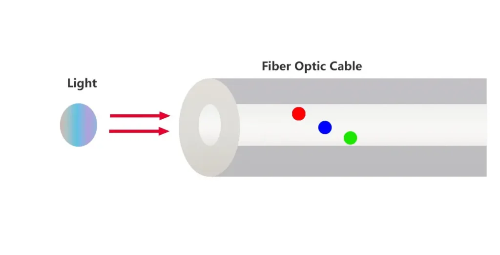
In my previous article, “How Fiber Optics Work: The Simple Science Behind Light,” I explained how light travels inside the fiber by constantly reflecting within the glass core. When light travels through an optical fiber, it doesn’t always stay perfectly synchronized.
Even though all signals move at nearly the speed of light, some parts of the signal arrive a little earlier or later than others. For example, blue light (short wavelength) transmits faster than red light (long wavelength). This tiny delay between different light components is what we call dispersion.
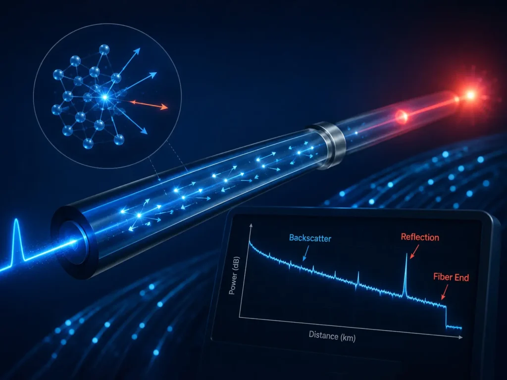
In simple terms, dispersion refers to the spreading of optical pulses as they propagate through a fiber. Instead of remaining short and sharp, each light pulse gradually broadens in time. When this happens, the receiver can no longer clearly distinguish between “0” and “1,” leading to potential bit errors.
You can imagine dispersion like a group of marathon runners who start together but don’t all reach the finish line at the same time. The longer the race (distance), the more spread out they become — and in fiber optics, that “spread” causes data signals to blur.
Why Dispersion Matters
Dispersion doesn’t reduce the power of the optical signal like attenuation does, but it distorts the shape of the transmitted pulses. When the pulses broaden too much, they begin to overlap, a phenomenon known as intersymbol interference (ISI).
This limits both the bandwidth and maximum transmission distance of a fiber optic link.
A simplified equation often used to describe pulse broadening is:
ΔT=D×Δλ×L
Where:
- ΔT = Pulse broadening (ps)
- D = Dispersion coefficient (ps/nm·km)
- Δλ = Spectral width of the light source (nm)
- L = Fiber length (km)
For example, if a laser has a 1 nm spectral width, and the fiber dispersion is 17 ps/nm·km, after 50 km the pulse will spread by 850 ps — enough to seriously distort high-speed signals.
Dispersion is one of the most critical parameters in designing high-speed optical communication systems, as defined in ITU-T G.650.3, which provides standardized measurement methods for chromatic dispersion.
Types of Dispersion in Optical Fibers
There are several mechanisms that cause light pulses to spread in fibers.
The four main types are:
- Material Dispersion
- Waveguide Dispersion
- Polarization Mode Dispersion (PMD)
- Intermodal Dispersion
Each of these affects the signal in a different way. Let’s begin with the first two, which are most common in single mode fibers.
Material Dispersion (Chromatic Dispersion)
Material dispersion occurs because different wavelengths (colors) of light travel at different speeds in the same material.
The refractive index of glass changes slightly with wavelength — blue light bends more than red light, and this small variation means that shorter and longer wavelengths reach the end of the fiber at different times.
In single mode fiber, even a tiny difference in refractive index (n) across the wavelength spectrum can cause measurable pulse spreading.
Mathematically, the dispersion coefficient due to material effects can be expressed as:

(Source: Govind P. Agrawal, “Fiber-Optic Communication Systems,” Wiley, 2012)
At around 1310 nm, the refractive index curve of silica glass flattens — meaning material dispersion is nearly zero. That’s why early optical systems were optimized for this wavelength.
However, at 1550 nm (where attenuation is lowest), material dispersion increases significantly, which required further engineering solutions like dispersion-shifted fibers.
Example analogy:
Think of a prism splitting white light into a rainbow — each color travels differently because each wavelength interacts with glass in its own way. Inside a fiber, this doesn’t create colors, but it does create timing differences.
Waveguide Dispersion
While material dispersion depends on the properties of the glass, waveguide dispersion depends on the geometry and structure of the optical fiber itself.
Light doesn’t stay perfectly inside the core; part of it travels through the cladding. Because these regions have different refractive indices, the overall propagation speed of the light depends on how much energy stays in the core versus how much leaks into the cladding.
Waveguide dispersion arises from this distribution of light energy between the two layers.
The formula for waveguide dispersion can be written as:

where β is the propagation constant, related to the fiber’s mode shape and structure.
By carefully designing the core diameter and refractive index difference, engineers can make waveguide dispersion cancel out the material dispersion — creating what is known as dispersion-shifted fiber (DSF), standardized under ITU-T G.653.
These fibers “shift” the zero-dispersion wavelength from 1310 nm to around 1550 nm, allowing low-loss and low-dispersion operation in the same window — ideal for long-haul transmission.
Polarization Mode Dispersion (PMD)
Even in a single mode fiber — where only one path of light should exist — not all light travels exactly the same way.
Light can have different polarizations, meaning its electric field can vibrate in slightly different directions.
In an ideal fiber, all polarizations would move at the same speed.
But in the real world, small imperfections in the fiber’s shape or external stresses (like bending or twisting) can cause different polarizations to travel at slightly different velocities.
This phenomenon is called Polarization Mode Dispersion (PMD).
The difference in arrival time between the two polarization states is called Differential Group Delay (DGD), usually measured in picoseconds (ps).
Mathematically, it can be approximated as:

Where:
- τPMD = Total polarization mode delay
- DPMD = PMD coefficient (ps/√km)
- L = Fiber length (km)
Typical PMD values for modern single mode fibers are around 0.1 ps/√km.
That might seem small, but in long-haul or high-speed systems (40 Gbps and above), even minor polarization delays can cause pulse overlap and bit errors.
You can think of it like two runners on parallel tracks — one slightly faster than the other. Over a long distance, even a tiny speed difference can cause one to lag far behind.
Intermodal Dispersion (Modal Dispersion)
While PMD happens in single mode fibers, intermodal dispersion occurs only in multimode fibers.
Multimode fibers have a much larger core (typically 50–62.5 µm), which allows multiple light paths — or “modes” — to travel simultaneously.
Each mode takes a slightly different route through the core: some go straight down the center, while others bounce off the walls at steeper angles.
Because these paths have different lengths, light traveling in each mode arrives at different times. This difference in arrival time is what causes intermodal (or modal) dispersion.
Approximation formula:

where:
- n₁ = core refractive index
- Δ = relative refractive index difference between core and cladding
- c = speed of light in vacuum
- L = fiber length
This form of dispersion is the main limitation of multimode fiber systems.
The more modes there are, the more spreading occurs — which limits transmission distance and bandwidth.
To mitigate this, engineers developed graded-index multimode fibers, where the refractive index gradually decreases from the center toward the edge.
This smooth profile helps equalize the travel time of different modes — so the light rays that take longer paths move faster, balancing out the delay.
As a result, modern OM3 and OM4 multimode fibers can carry high-speed signals (10–40 Gbps) for hundreds of meters with acceptable dispersion performance.
How to Manage and Compensate for Dispersion
Dispersion cannot be completely eliminated, but it can be managed and compensated.
Here are several techniques used in modern optical systems:
- Dispersion Compensating Fiber (DCF)
A special type of fiber designed with negative dispersion, used in series with transmission fiber to offset total chromatic dispersion.
Common in long-haul systems before the era of digital compensation. - Dispersion Compensation Modules (DCM)
Compact optical devices (using fiber gratings or lenses) that reverse the dispersion accumulated over long distances.
They’re often installed in repeaters or amplifiers. - Electronic and Digital Signal Processing (DSP)
Modern transceivers can detect and digitally correct dispersion effects in real time, greatly improving performance for high-speed systems (100G and beyond). - Fiber Design Optimization
By combining material and waveguide dispersion, fiber designers can create “zero-dispersion wavelength” fibers such as G.653 (Dispersion-Shifted Fiber) and G.655 (Non-Zero Dispersion-Shifted Fiber).
These fibers minimize dispersion at key wavelengths, allowing efficient DWDM (Dense Wavelength Division Multiplexing) transmission.
Effects of Dispersion on Network Performance
Dispersion directly impacts how far and how fast data can travel in fiber optic networks.
Some of the most common effects include:
- Pulse broadening – Light pulses overlap, making it hard to distinguish bits.
- Reduced bandwidth – The data rate must be lowered to avoid errors.
- Higher bit error rate (BER) – Overlapping pulses cause incorrect data interpretation.
- System synchronization issues – Delay differences between channels reduce timing accuracy.
For example, in a 10 Gbps system, a chromatic dispersion of 17 ps/nm·km over 80 km can cause pulse broadening of over 1.3 ns — roughly the duration of 13 bits — enough to cause major signal distortion.
That’s why managing dispersion is essential in every stage of network design, from choosing fiber types to selecting compatible connectors, adapters, and splicing methods.
FAQ: Dispersion in Fiber Optics
What causes dispersion in optical fibers?
Different wavelengths and modes of light travel at different speeds due to the fiber’s material and geometry — leading to pulse spreading.
Which type of dispersion affects single mode fiber the most?
In single mode fibers, chromatic dispersion (material + waveguide) and polarization mode dispersion (PMD) are the main contributors.
What is the main cause of intermodal dispersion?
Multiple light modes taking different paths through the core of a multimode fiber
How can dispersion be reduced?
By using dispersion-compensating fibers or modules, choosing the right fiber type (e.g., G.652D, G.655, or G.657), and using narrow-spectrum lasers.
Why is dispersion important in long-distance networks?
Because pulse broadening accumulates with distance — without control, high-speed signals become distorted and unreadable after long transmission.
In Summary
Dispersion is not an error — it’s a natural property of light in glass.
But if left unmanaged, it can blur signals, limit bandwidth, and degrade network performance.
By understanding the four main types — material, waveguide, polarization mode, and intermodal dispersion — engineers can design more reliable and efficient communication systems.
With the right fiber type, optimized installation practices, and modern compensation technologies, dispersion can be effectively controlled, allowing light to deliver information cleanly and precisely — even over thousands of kilometers.